
To be installed by a licensed, professional, experienced plumber or installer.
To ensure that your new ScaleStop Plus water filtration system is properly installed, we offer free installation technical support by a master installer, Shannon Chisholm.
When you schedule the installation, text message Shannon Chisholm and let him know the date and time of the installation. At the start of the installation, have your plumber or installer call Shannon Chisholm for installation support.
⚠️ Important It is crucial that your plumber or installer consult with our master installer during installation. Failure to do so will not activate the warranty.
⚠️ Important The water filtration system must always remain upright during transportation, installation, and operation.
Use plumber’s grease between metal-to-metal fittings, on O-Rings, and on lock nuts, for a better seal and to prevent water leaks. (Use a plumber’s grease that is rated for rubber O-Rings.)
⚠️ Hand tighten lock nuts on Bypass Valves and Hoses. Do not use a wrench.
Always turn the water main valve, shut-off valve, and bypass valves slowly to gradually pressurize the system.
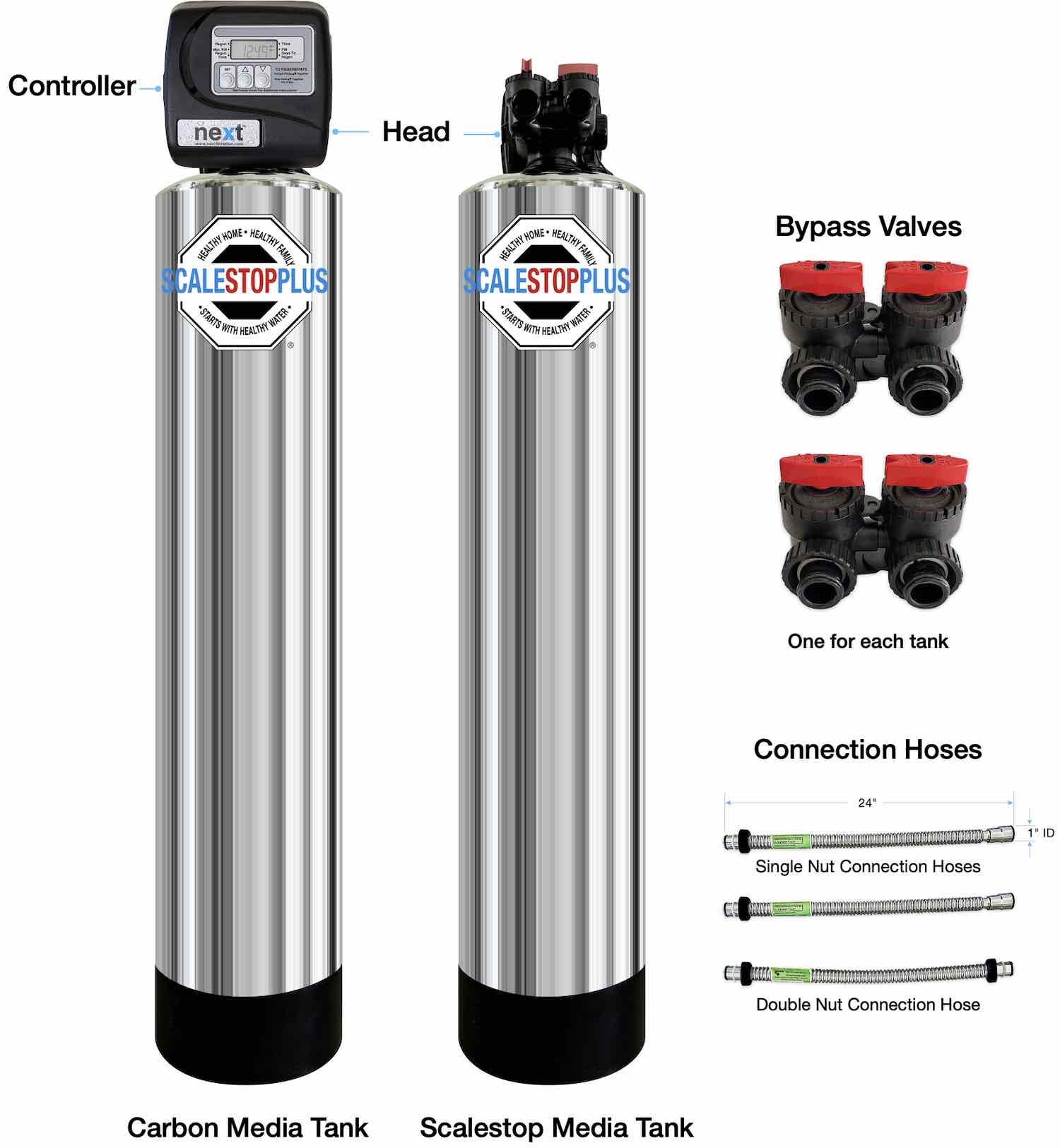
The ScaleStop Plus water filtration systems with dual tanks include the parts shown below.
How do you distinguish between the Carbon Media Tank and the ScaleStop Media Tank? The Carbon Media Tank comes equipped with the Controller.
| Carbon Media Tank Information |
|---|
| Equipment is limited to use at water pressures not to exceed 100 PSI and temperatures not to exceed 110℉. |
| Do not use on water that is has bacteria or is contaminated with coliform or e.coli. |
| Effectively removes chlorine, enhancing water taste, and eliminates odors. |
| Alleviates skin irritations and allergic reactions related to chlorine. |
| Allows you to enjoy showers without the harshness of chlorine. |
| A minimum of 20 pounds of water pressure is required for proper operation. The acceptable operating pressure is 15 psi - 100 psi (103 kPa - 689 kPa). |
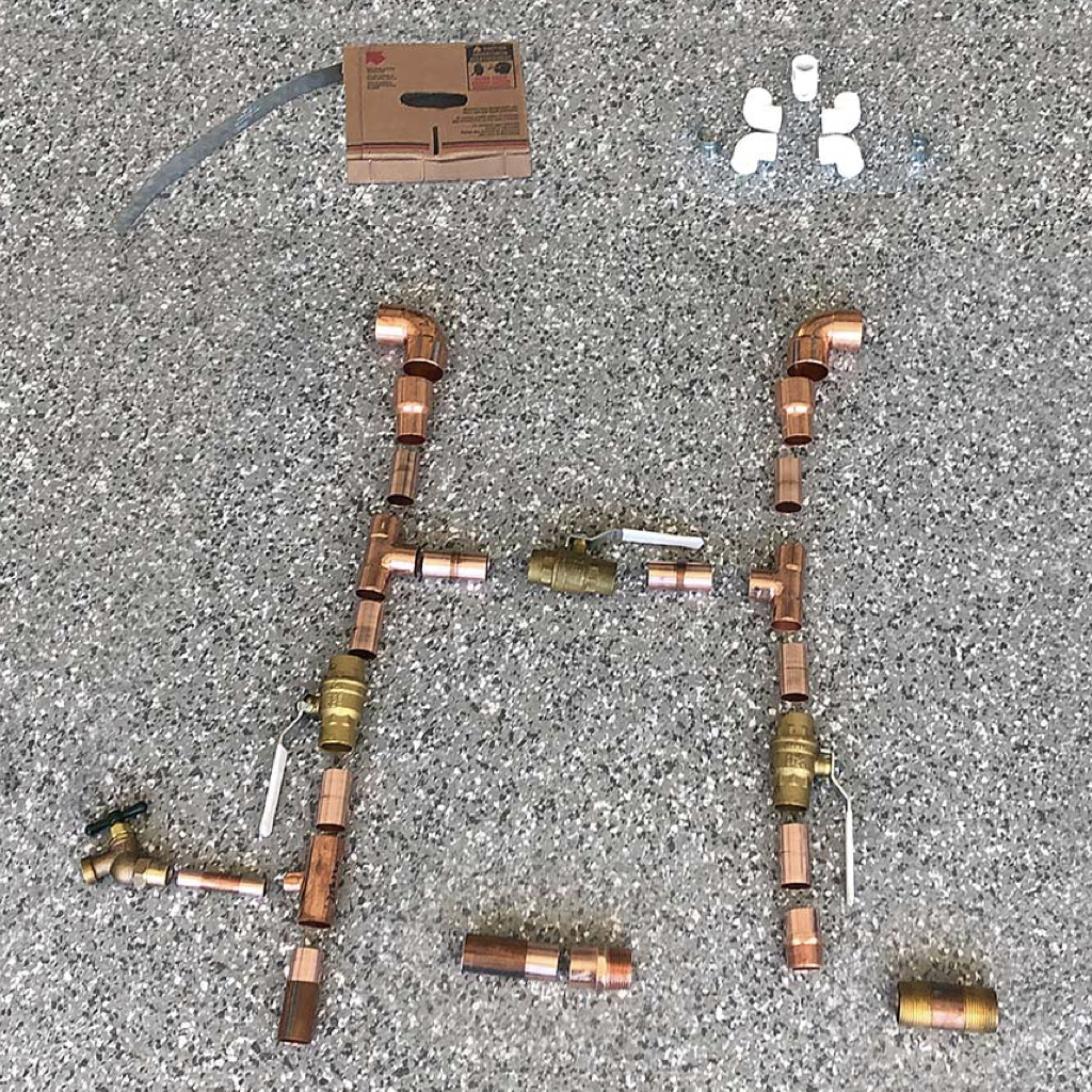
In addition to the parts included with the ScaleStop Plus water filtration system, the installer will need to supply additional parts, such as the parts shown below.
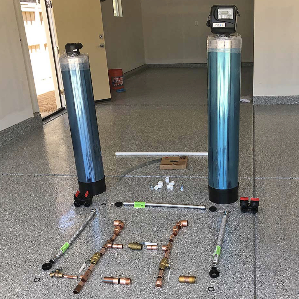
The installer will need to supply additional parts during installation, such as the parts shown below.
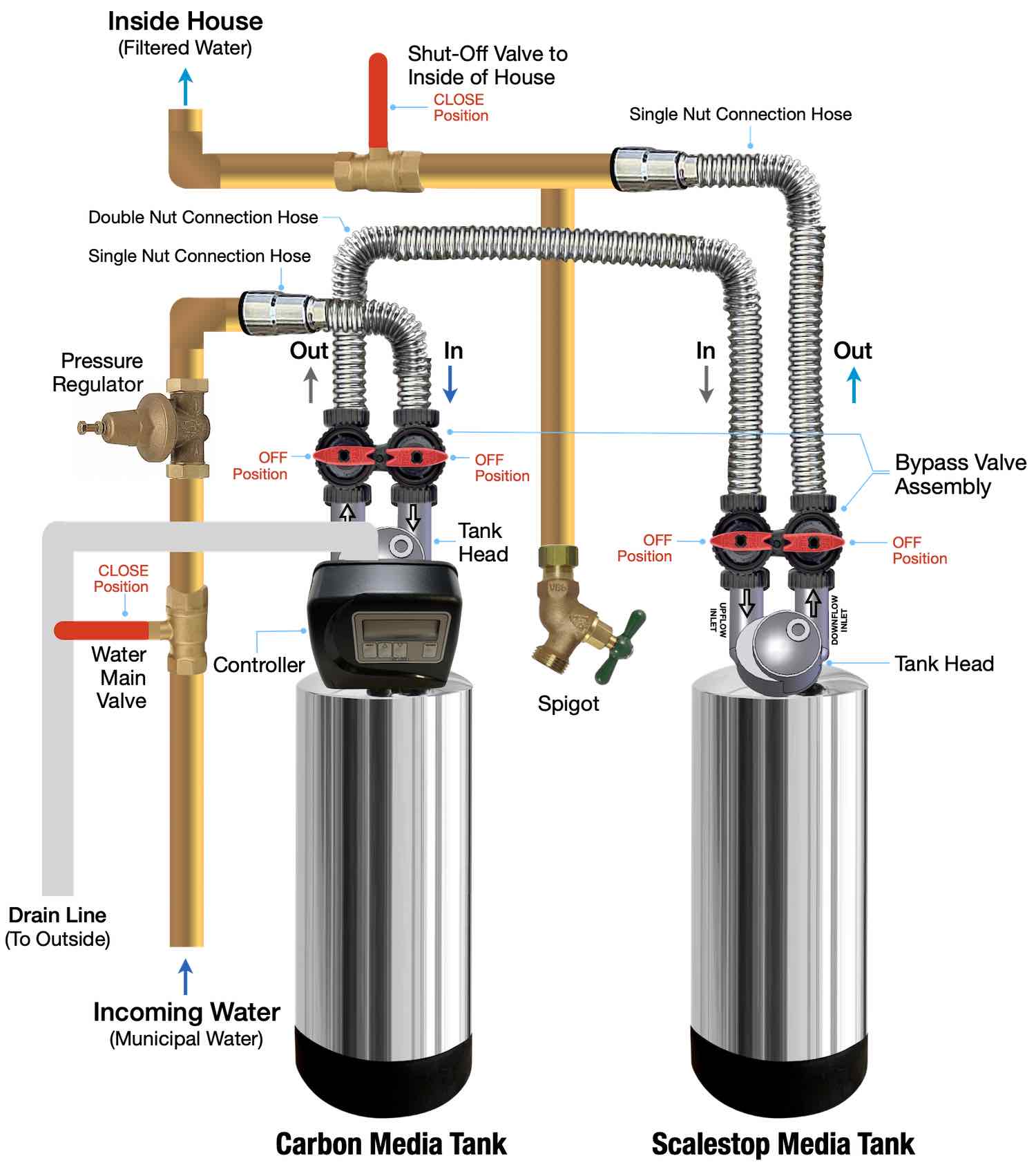
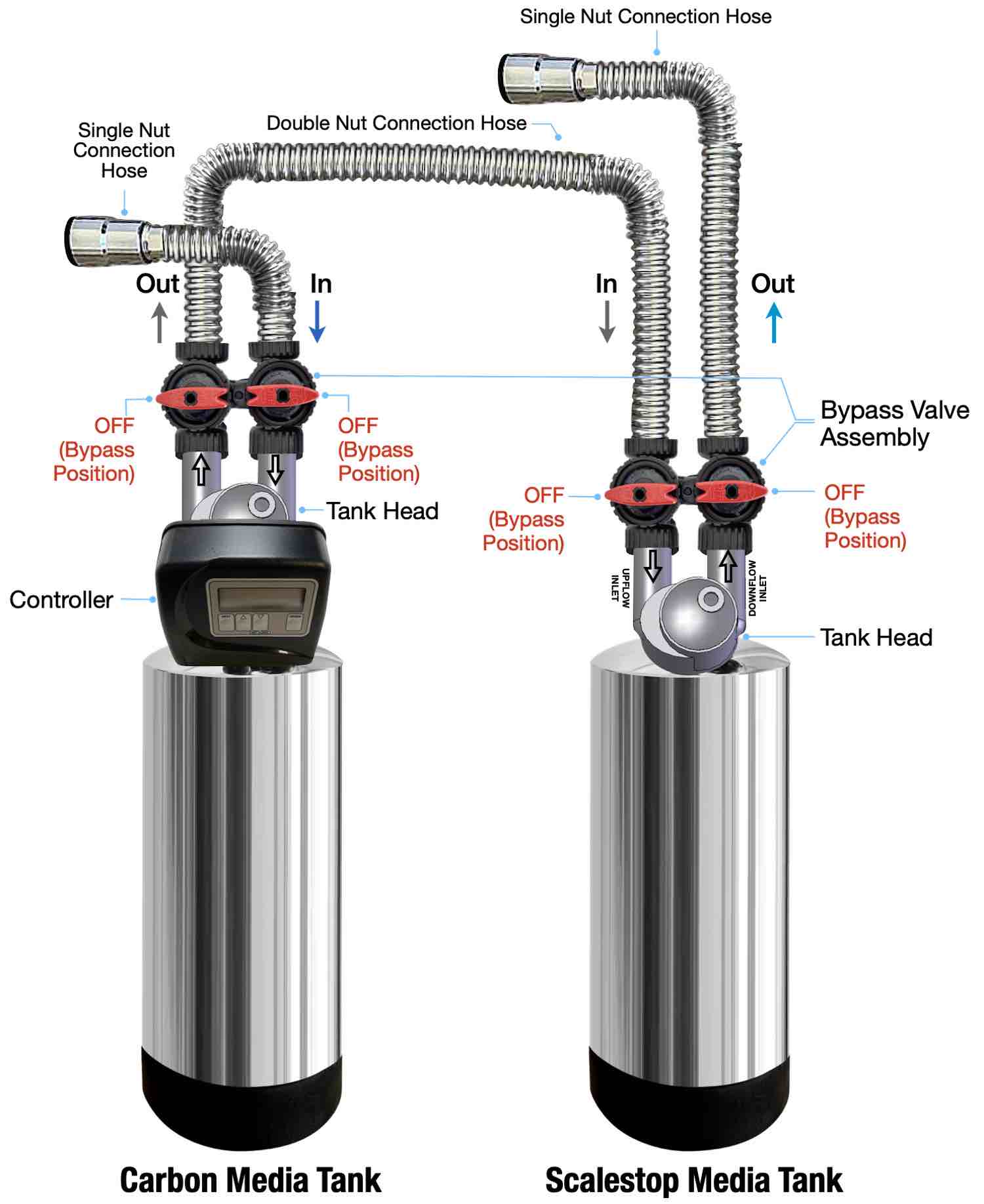
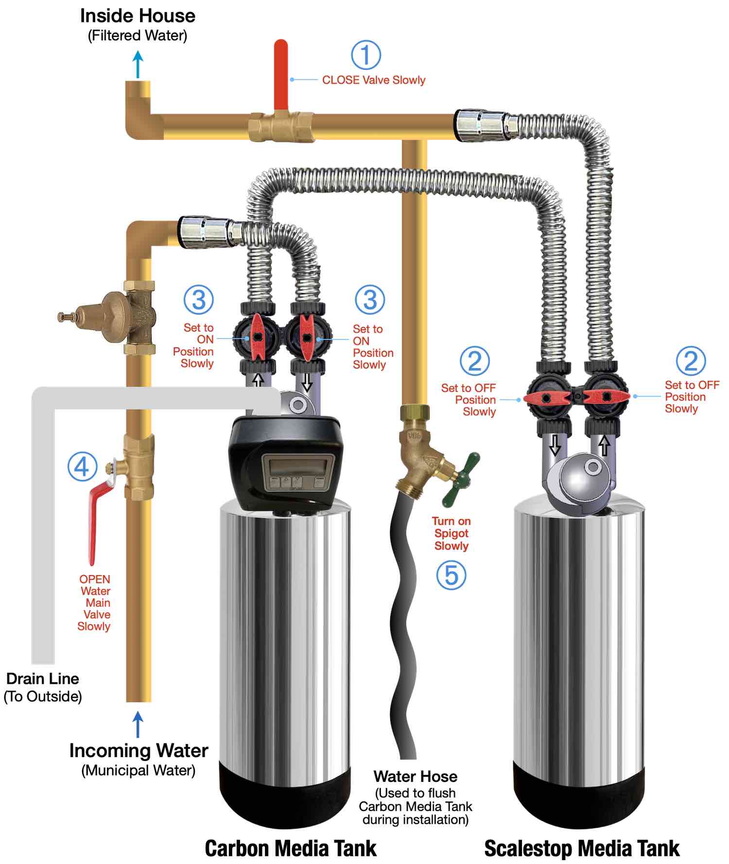
The diagram below shows the completely connected water filtration system, but not yet operational.
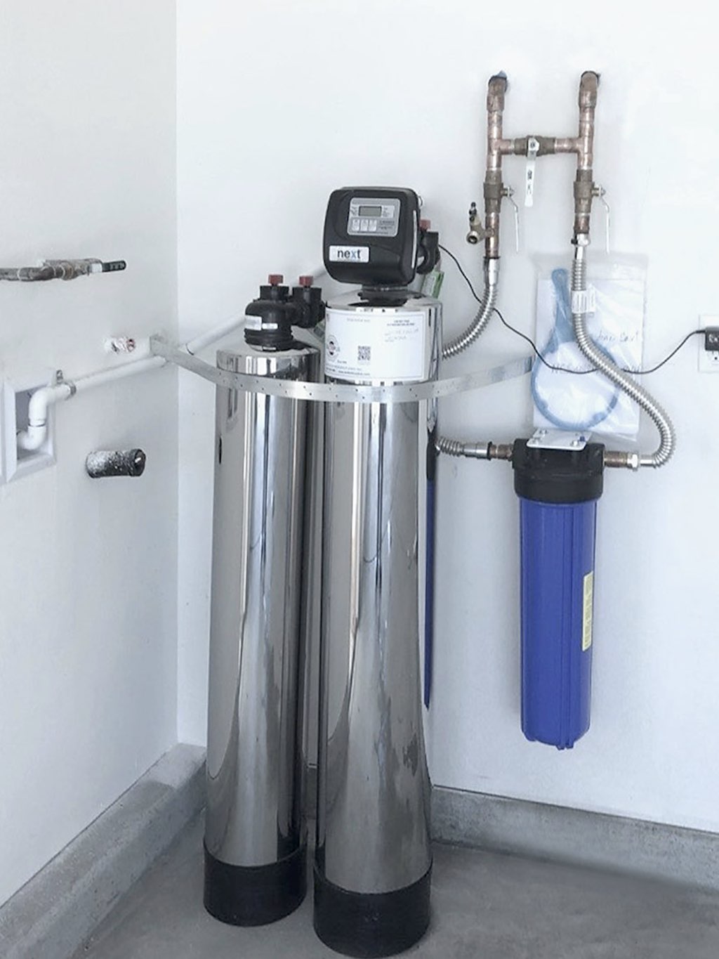
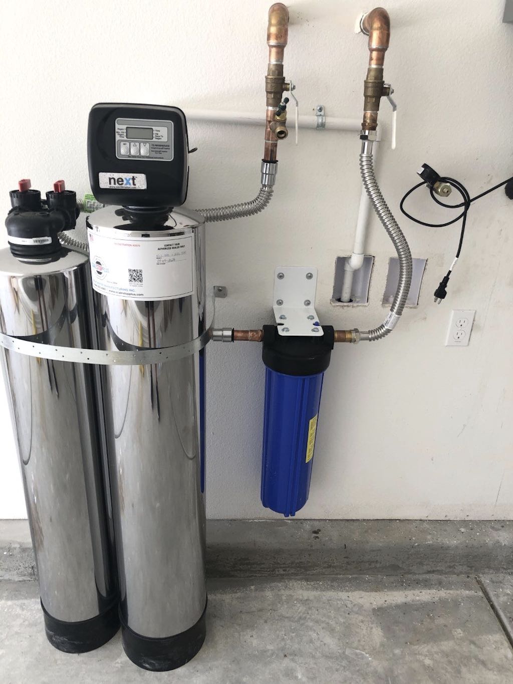
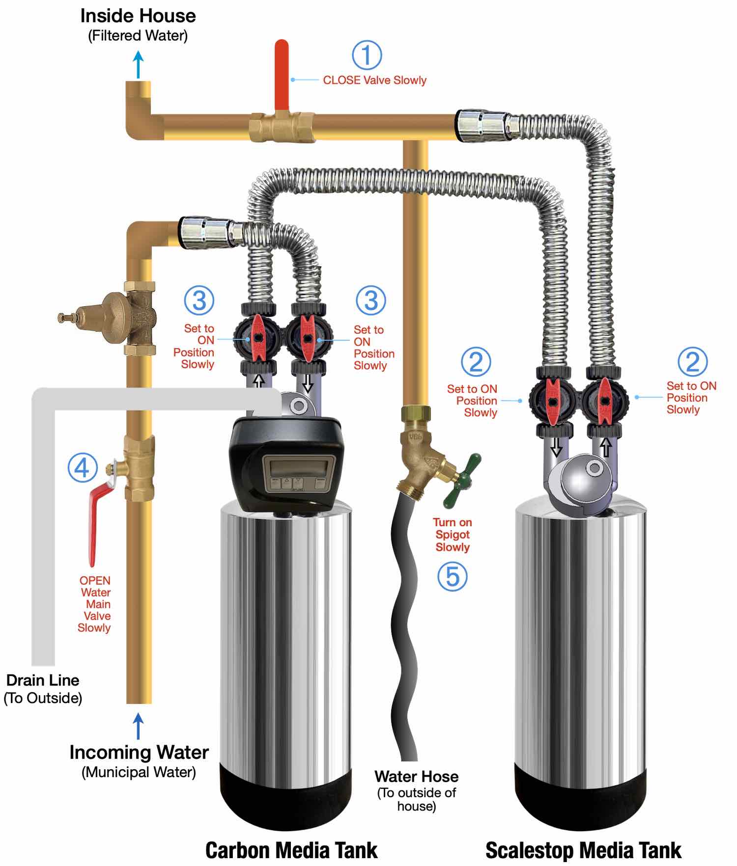
The diagram below shows the complete water filtration system when it is fully installed and operational.
In operational mode, all the valves ➀ ➁ ➂ ➃ are OPEN or ON. Especially note the direction of the Red Arrow Handles ➁ and ➂.
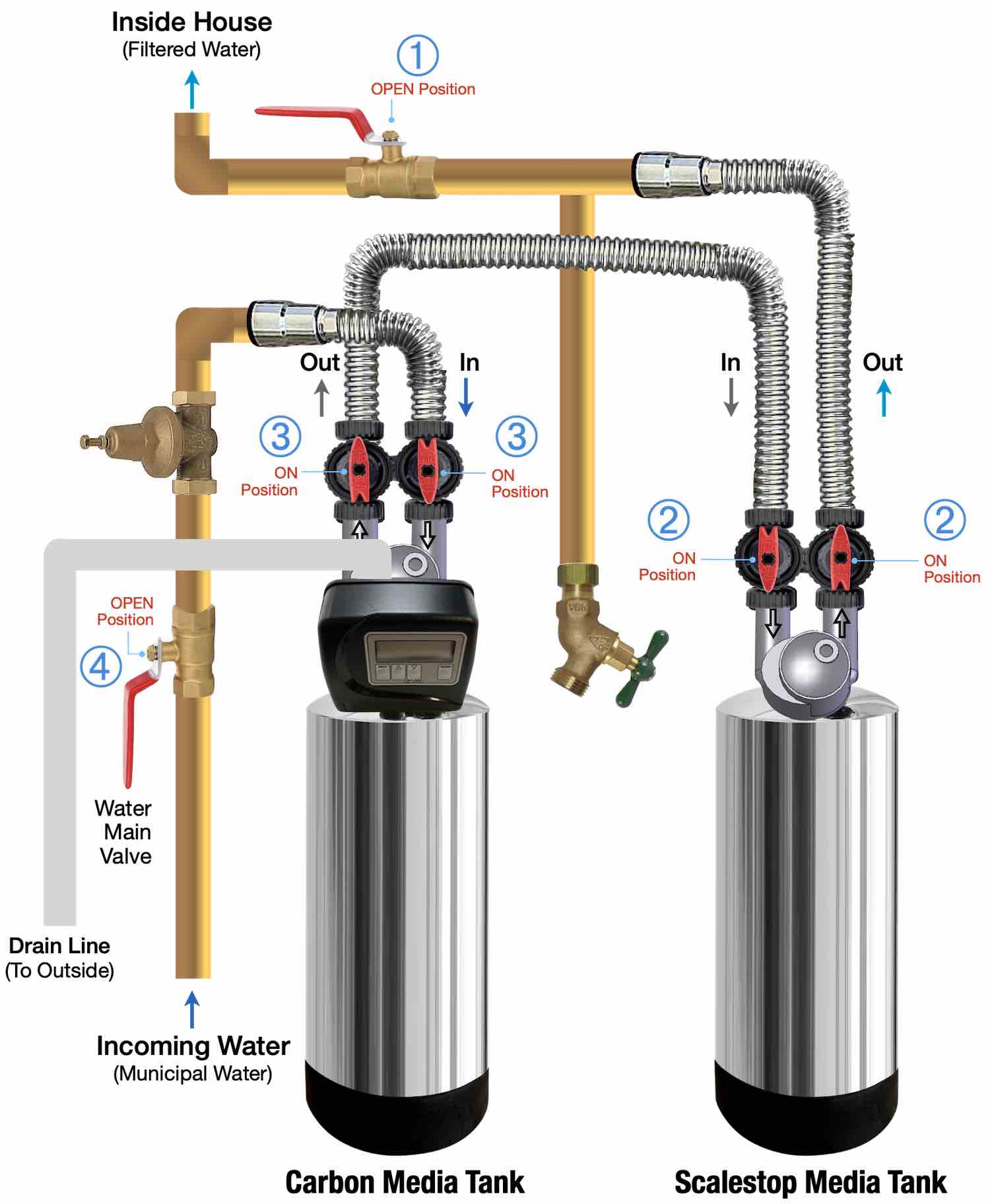
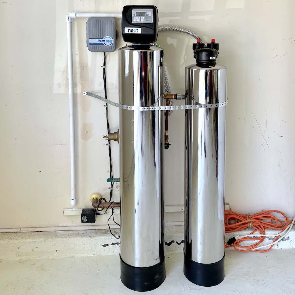
The Controller is plugged into the electrical outlet.
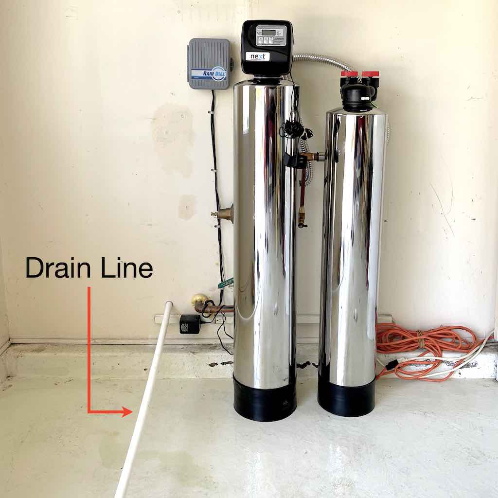
The drain line drains to outside the house.
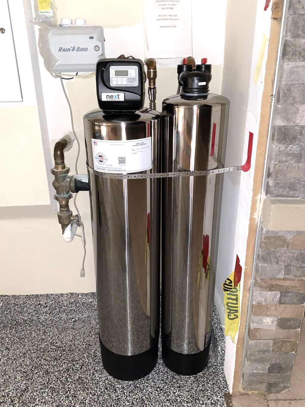
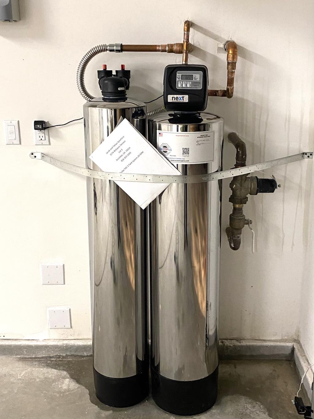
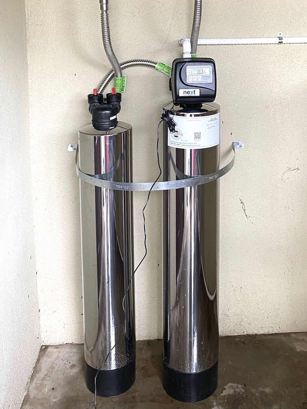
A metal strap is used to secure the tanks.
A whole-house water filtration system is installed at the point where the source water comes into your house, so it can filter all the water that flows within your house.
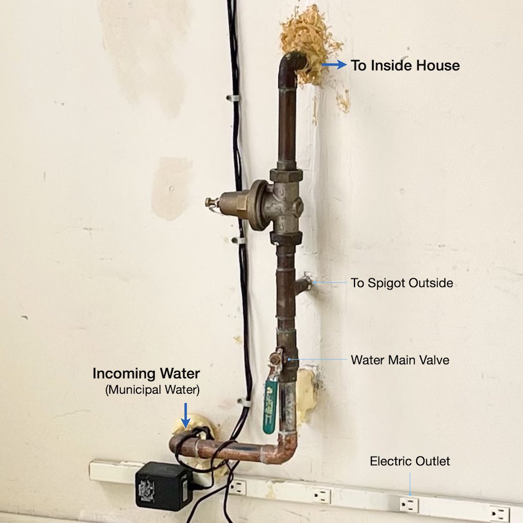
Choose the location where the water filtration system will be installed.
The location where you will be installing the water filtration system should:
Clear the site where you will be placing the water filtration tanks.
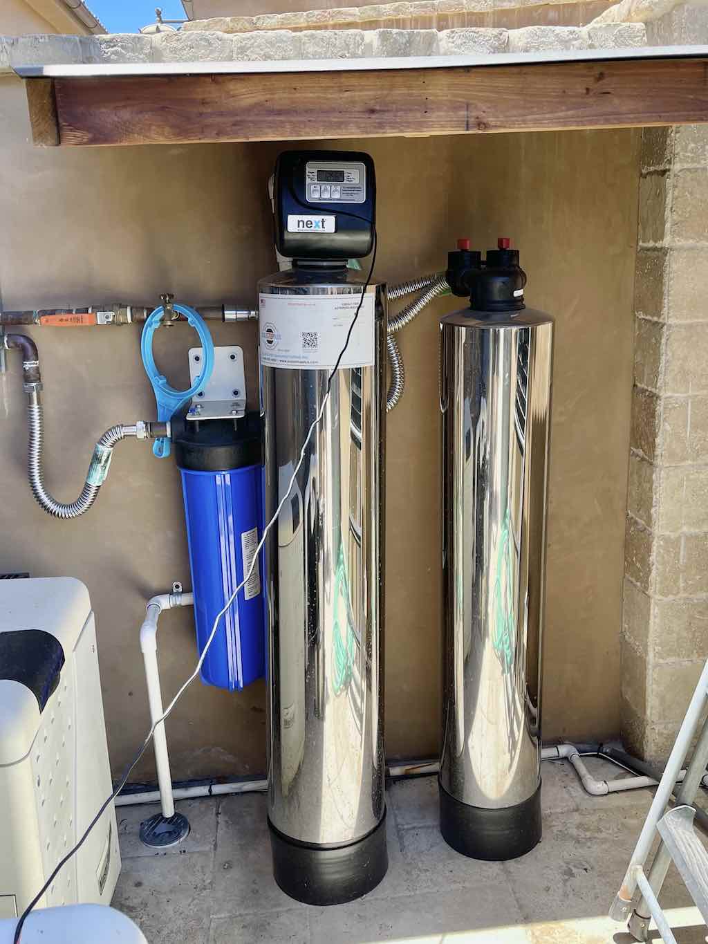
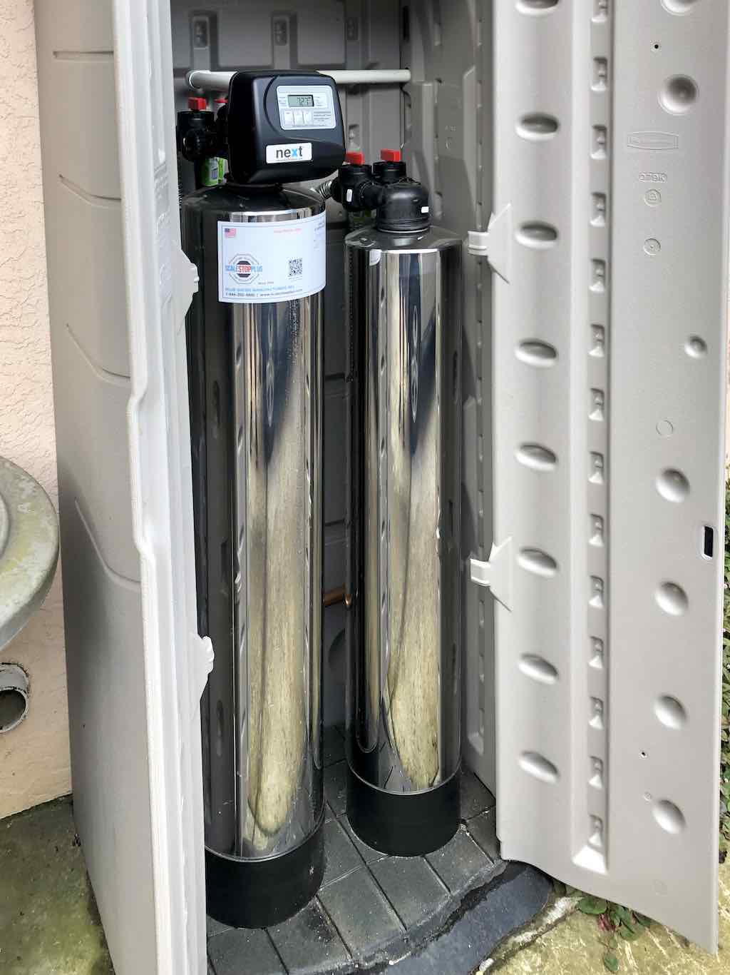
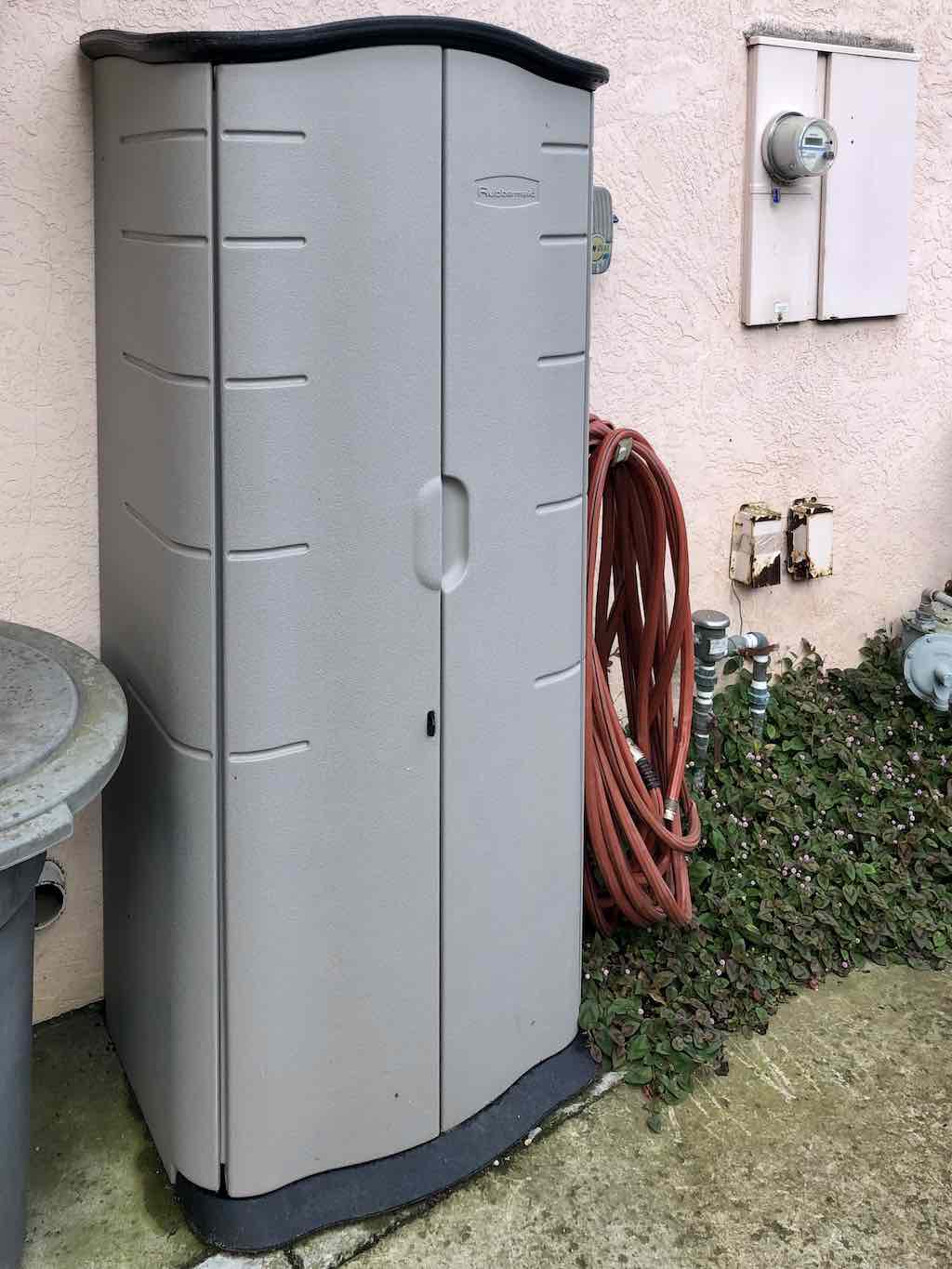
⚠️ Caution It is highly recommended that the water filtration system be installed inside in a covered area. If the water filtration system is installed outside, it should be in a properly covered and protected area.
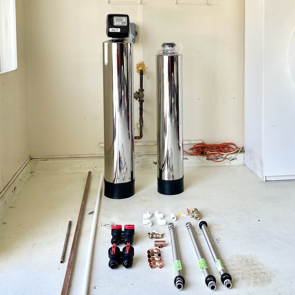
Place the parts to be installed at the location site:
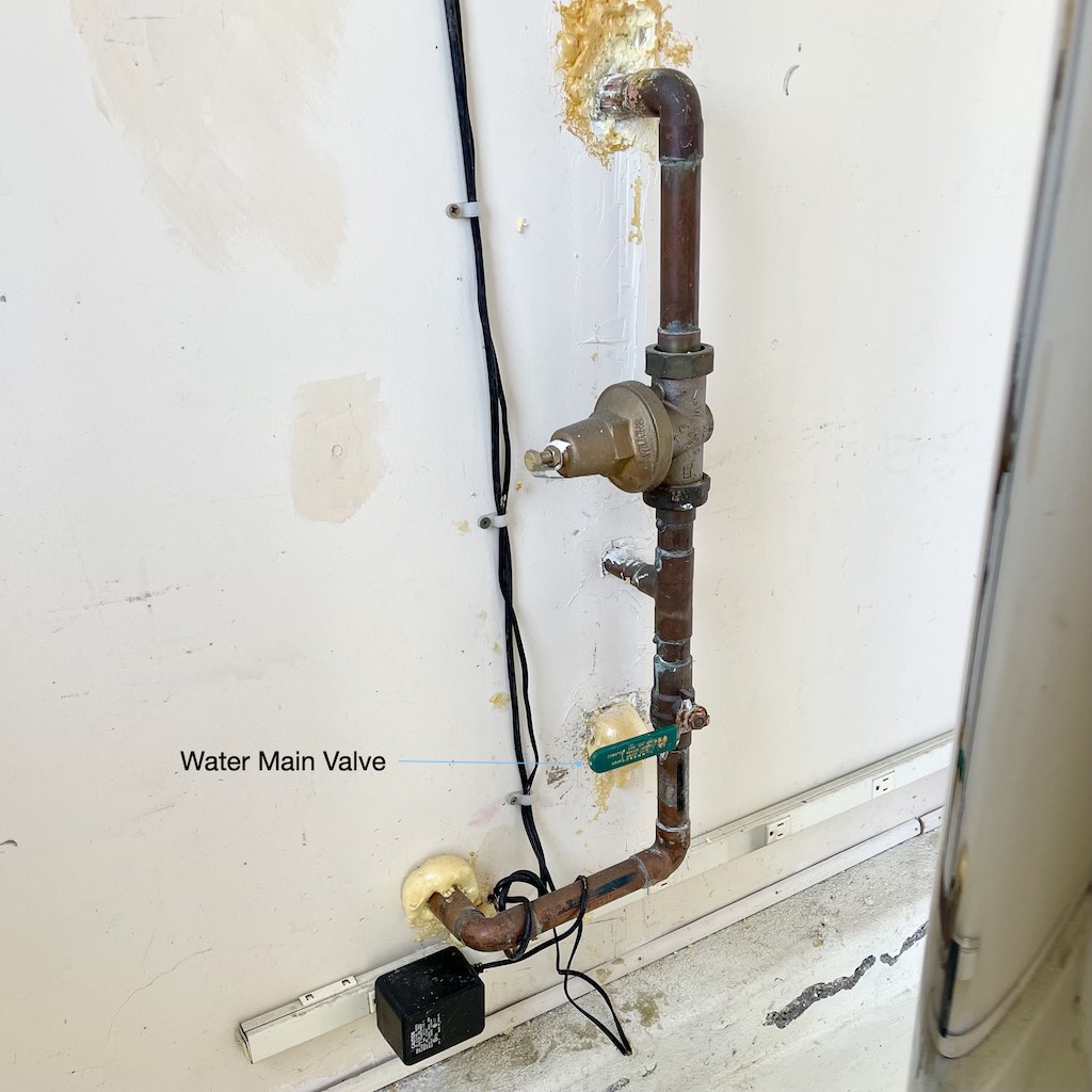
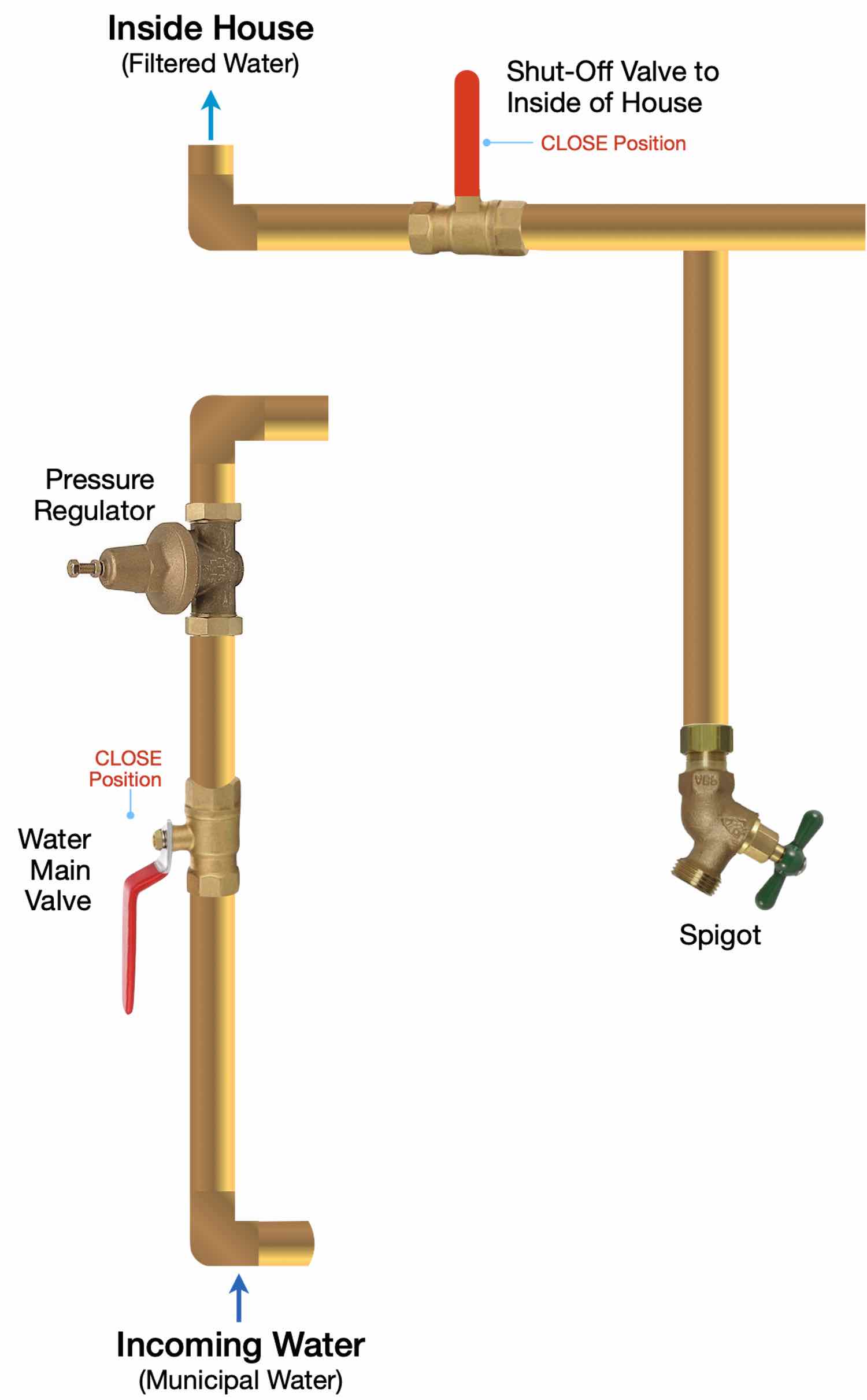
Turn the Water Main Valve Lever to the CLOSE position (perpendicular to the water pipe).
Drain the plumbing by turning on faucets around the house until no water flows. Then turn the faucets off.
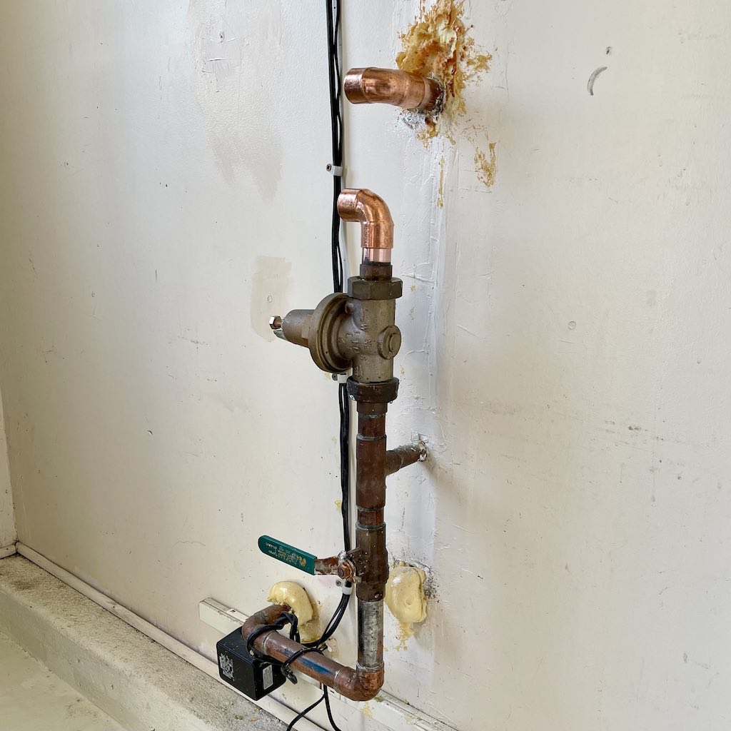
The next few steps involve cutting, preparing, and connecting the copper piping for the water filtration system. Below is an example of a copper piping connections diagram. Your connections and installation may vary due to the manner in which your piping has been plumbed.
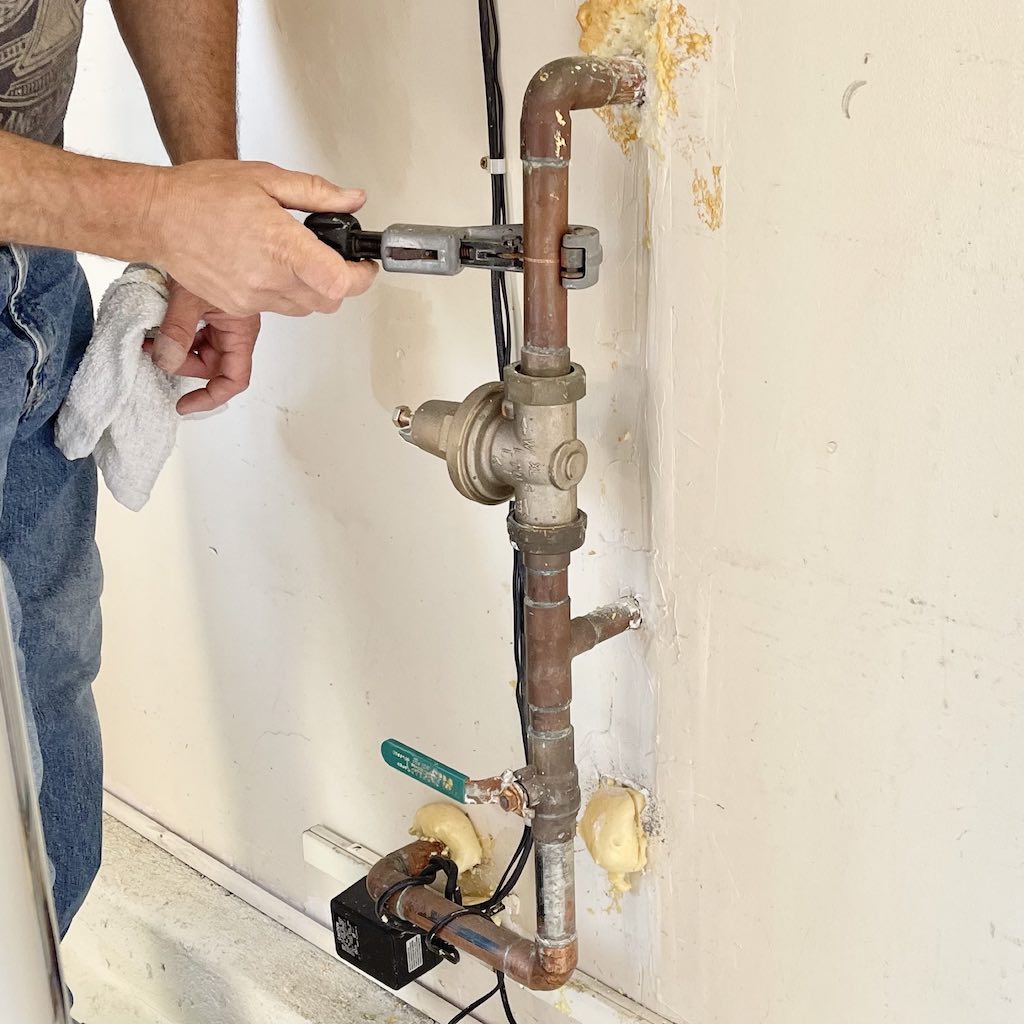
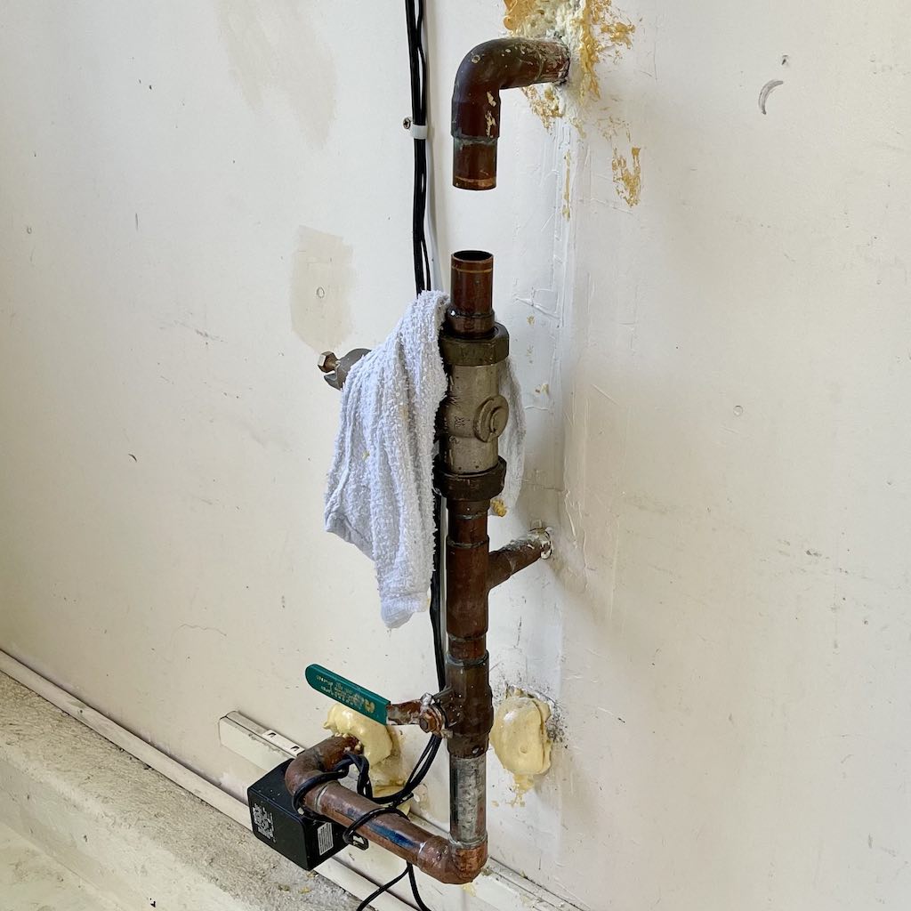
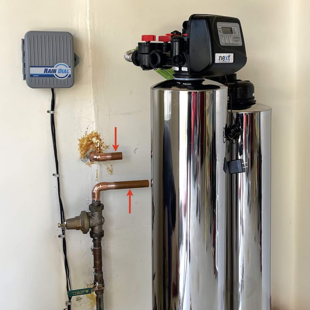
Use a tool to score the copper pipe above the water pressure regulator.
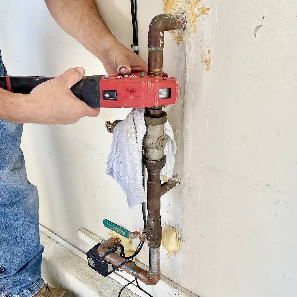
Use a cutting tool to cut the copper pipe above the water pressure regulator.
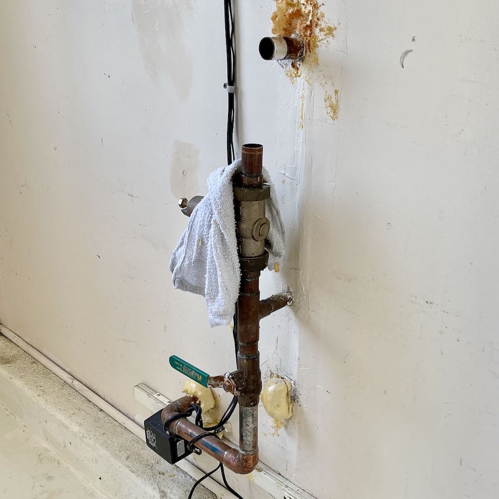
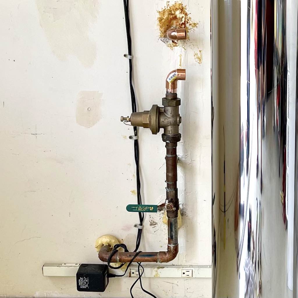
Remove existing elbow joint.

Sand down copper pipe to prepare it to accept a new elbow joint.
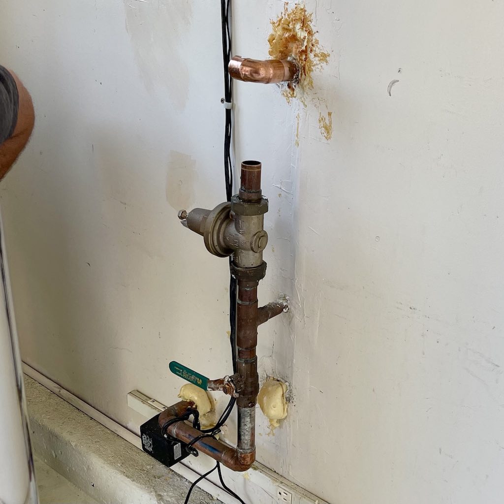
Insert new elbow joint.
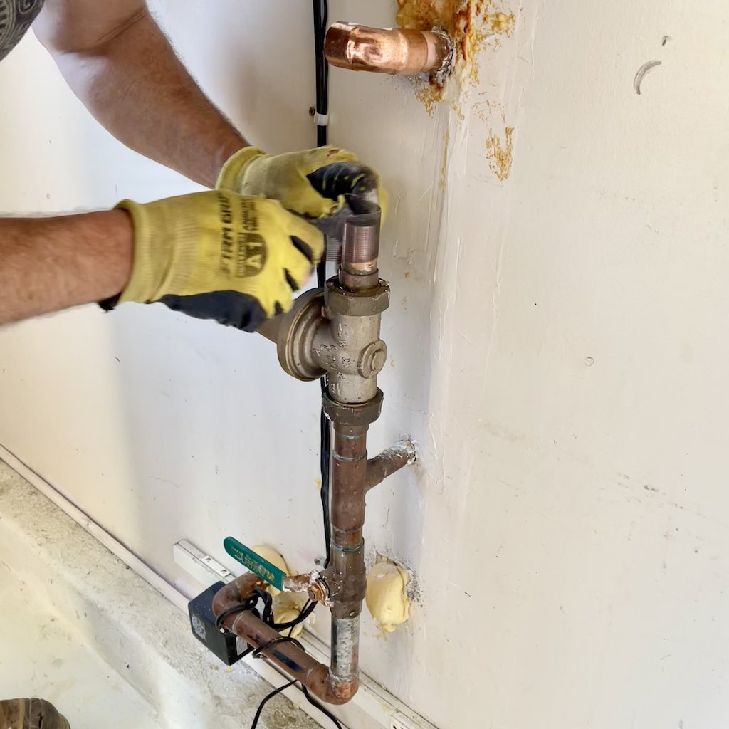
Sand down copper pipe to prepare it to accept a new elbow joint.
Insert new elbow joint.
Adjust the orientation of the two new elbow joints.
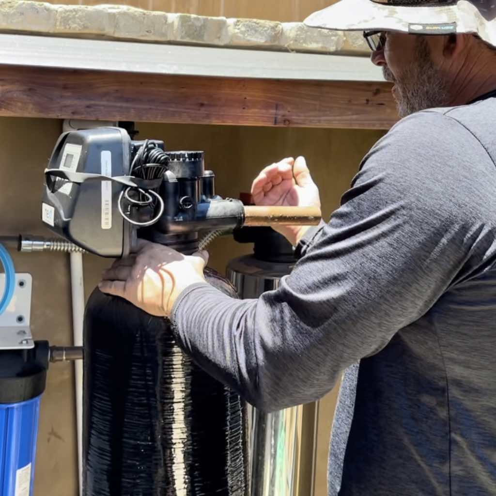
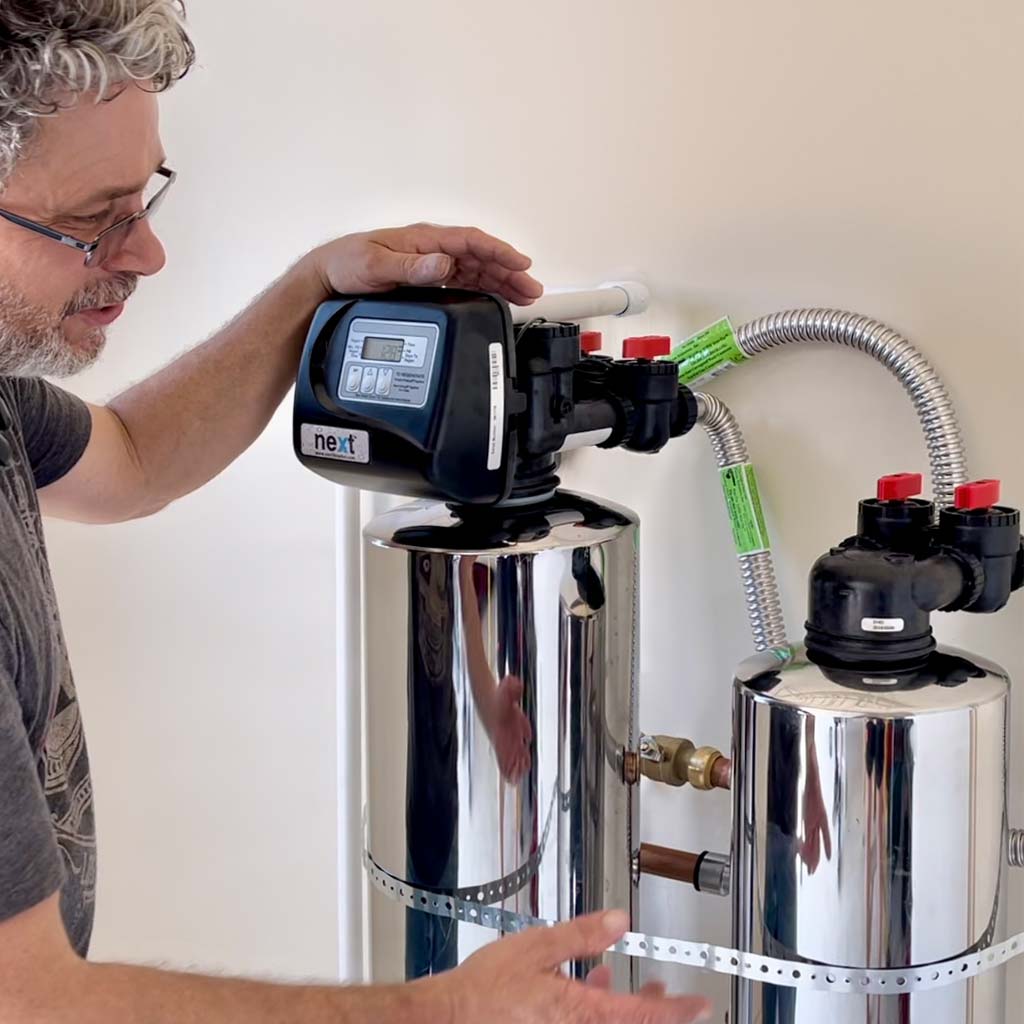
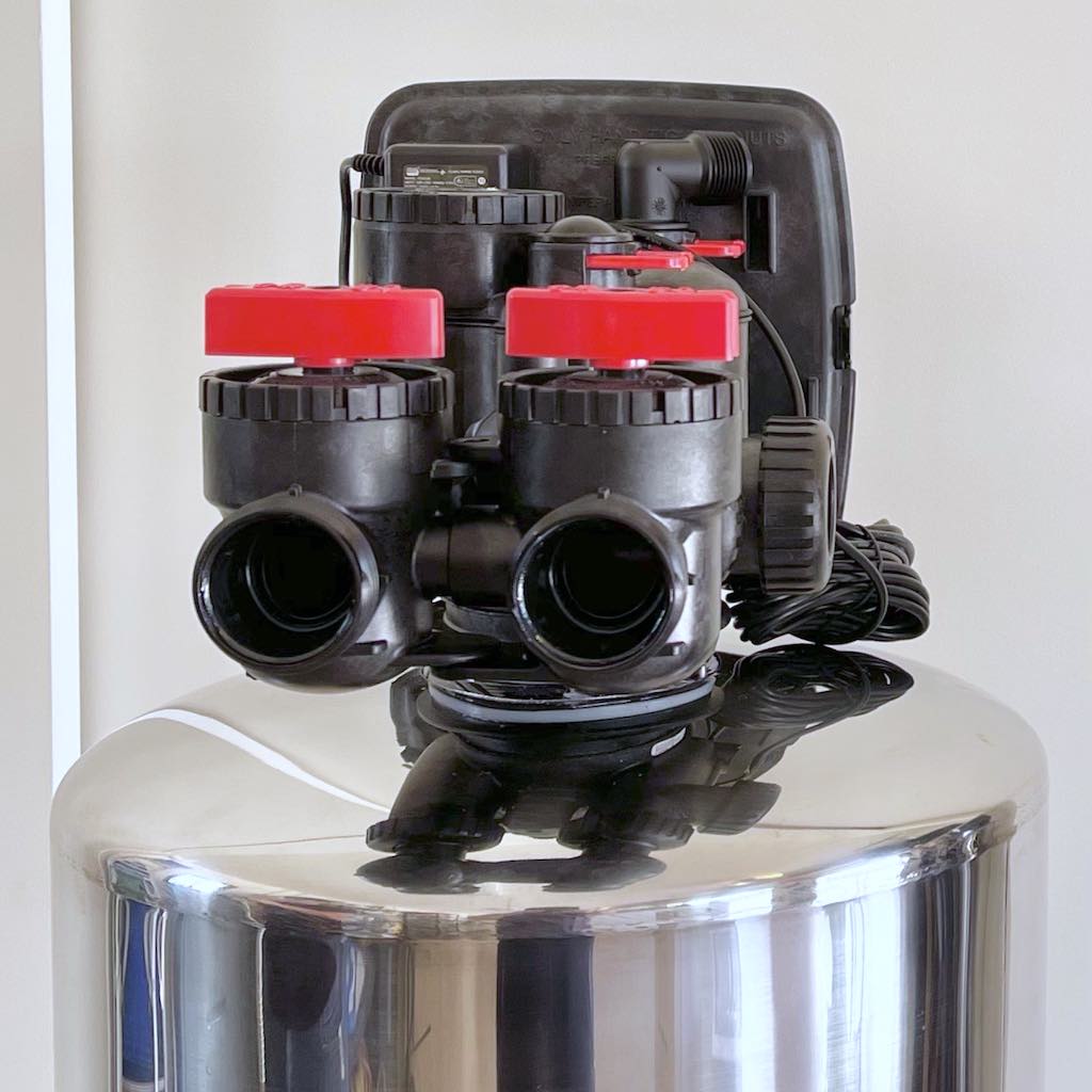
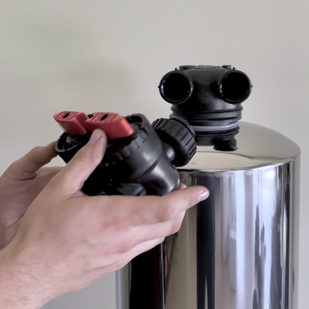
Each tank is delivered with the Head installed at the top. Before attaching the connection hoses, tighten the Head of both tanks to prevent leaks.
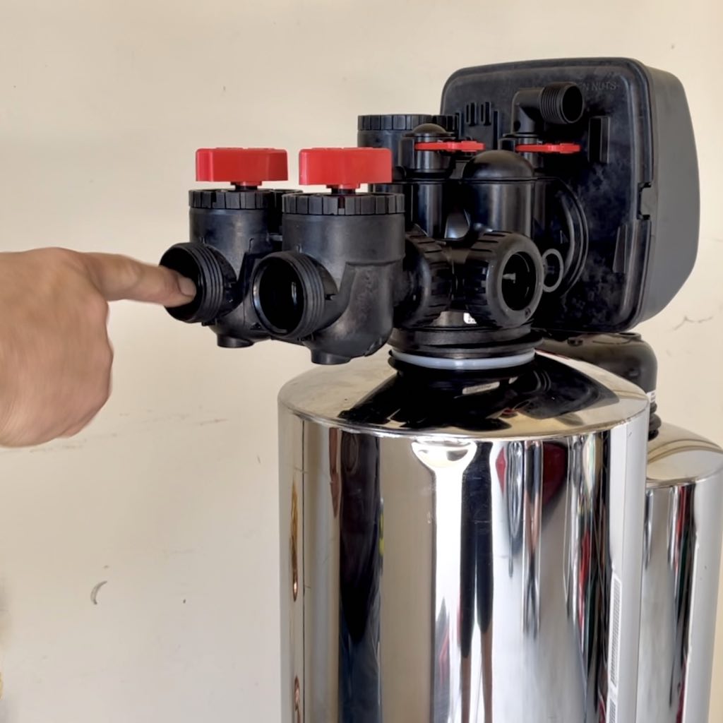
The Carbon Media Tank is distinguished from the ScaleStop Media Tank by the Controller that it has on top.
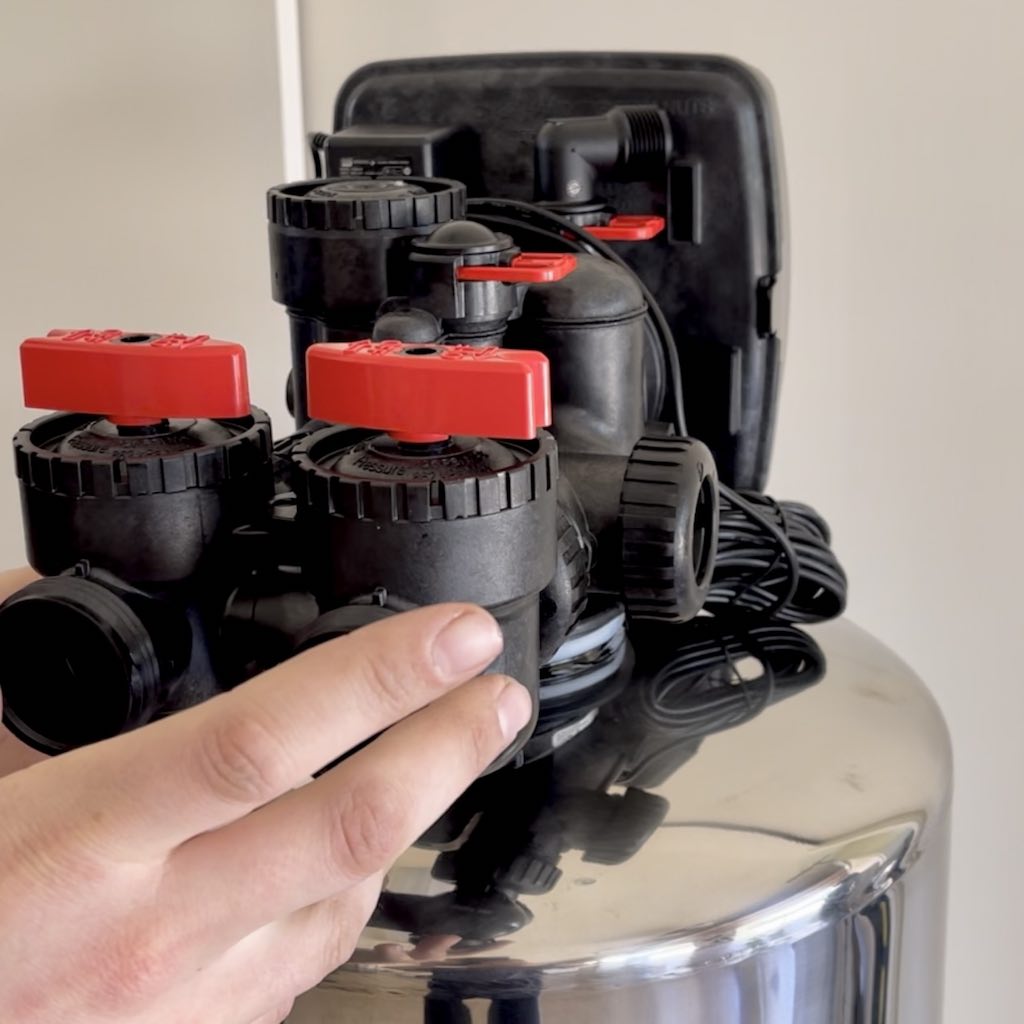
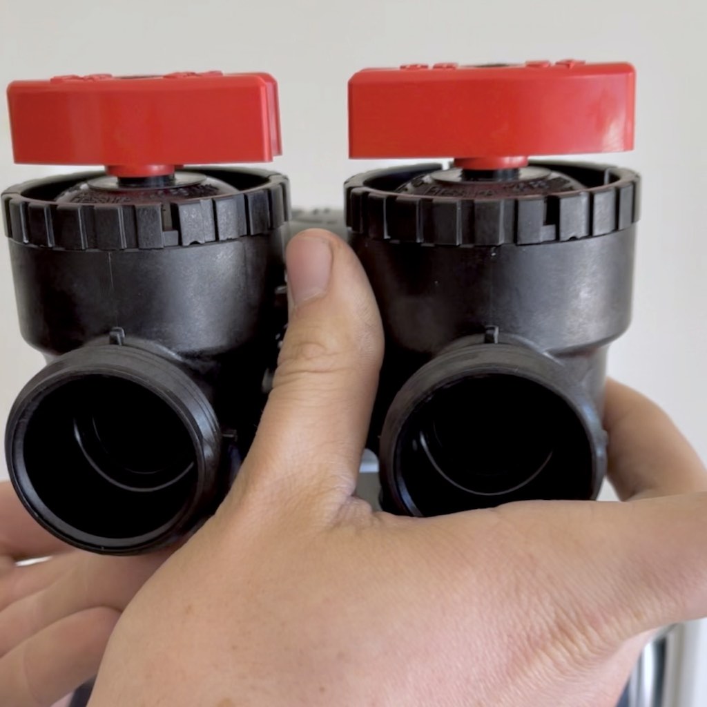
Notice the OFF and ON positions of the large red arrow handles of the Bypass Valves.
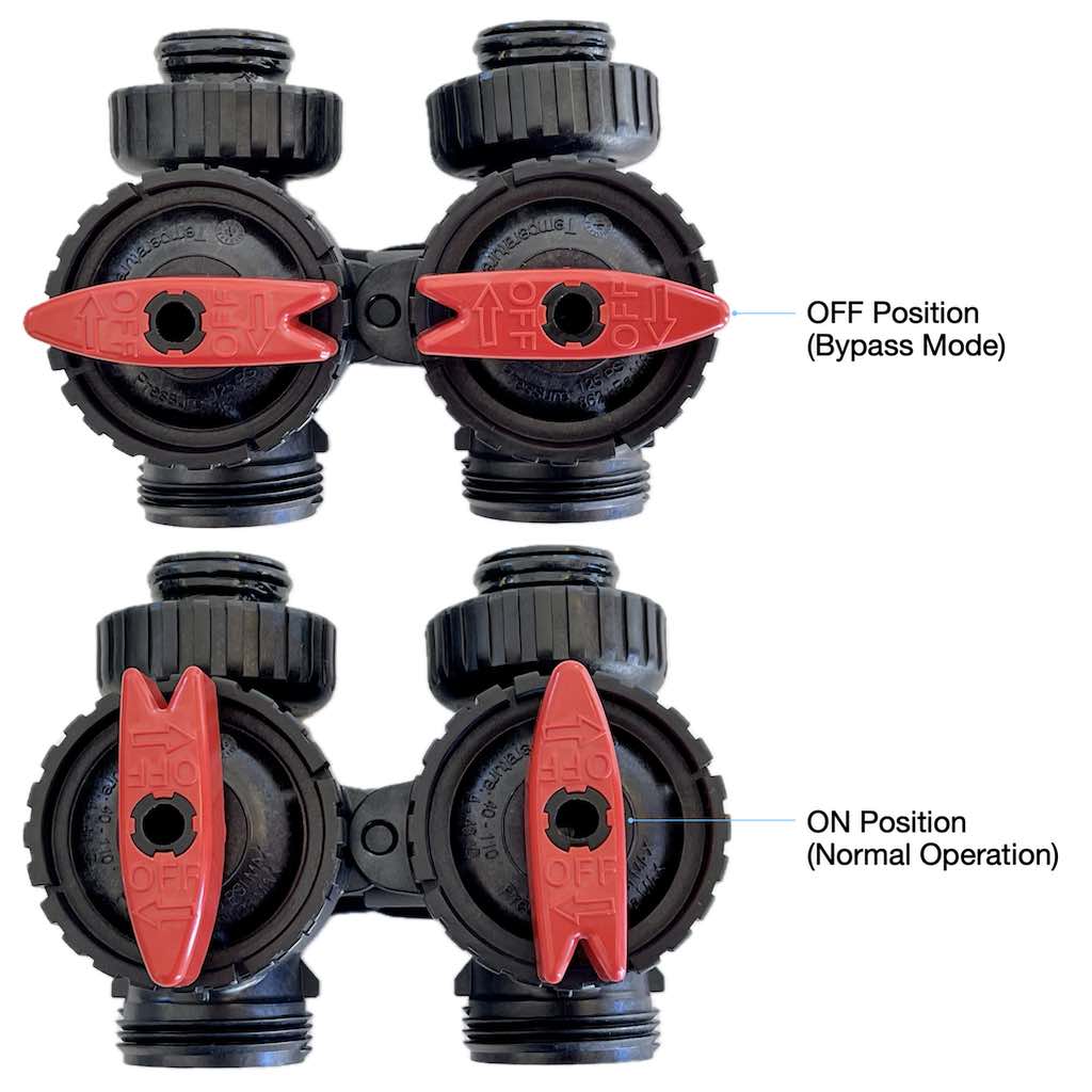
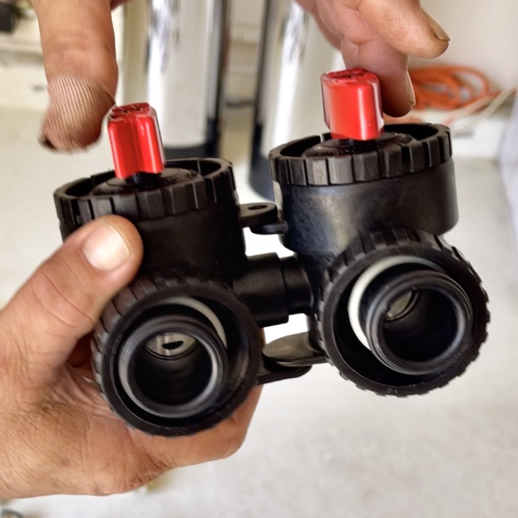
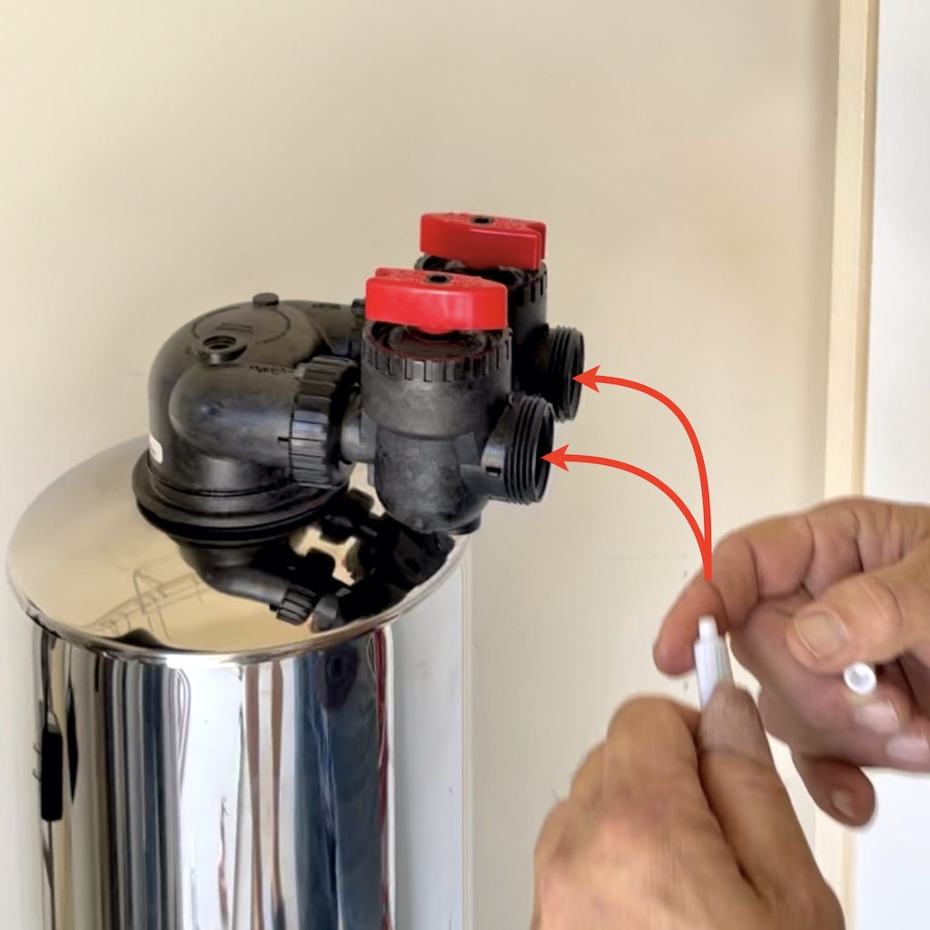
Check Bypass Valve to ensure that the orientation is correct (view video below for details).
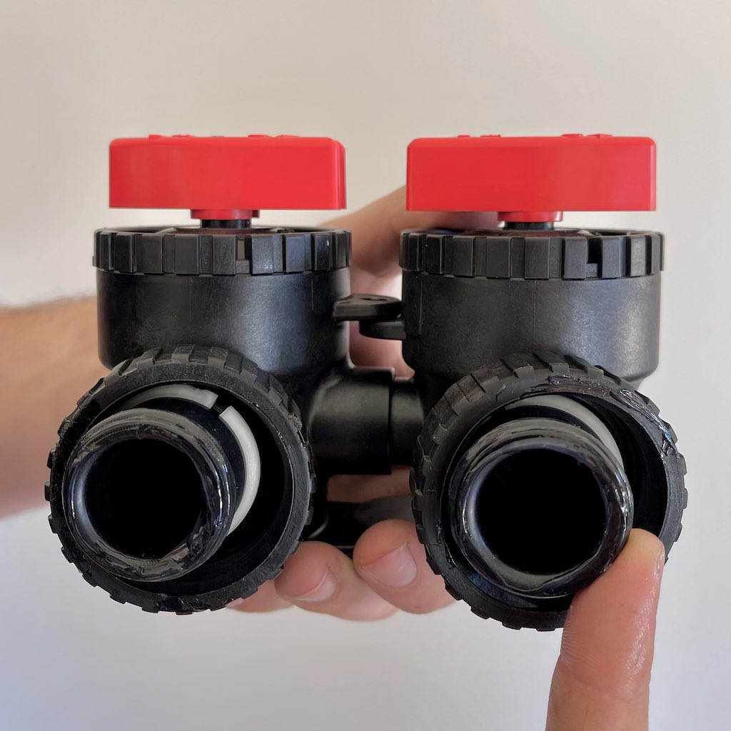
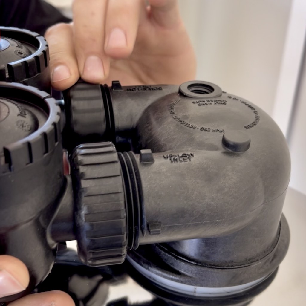
Apply plumber's grease all the way around the exterior threads of both openings of the Bypass Valve.
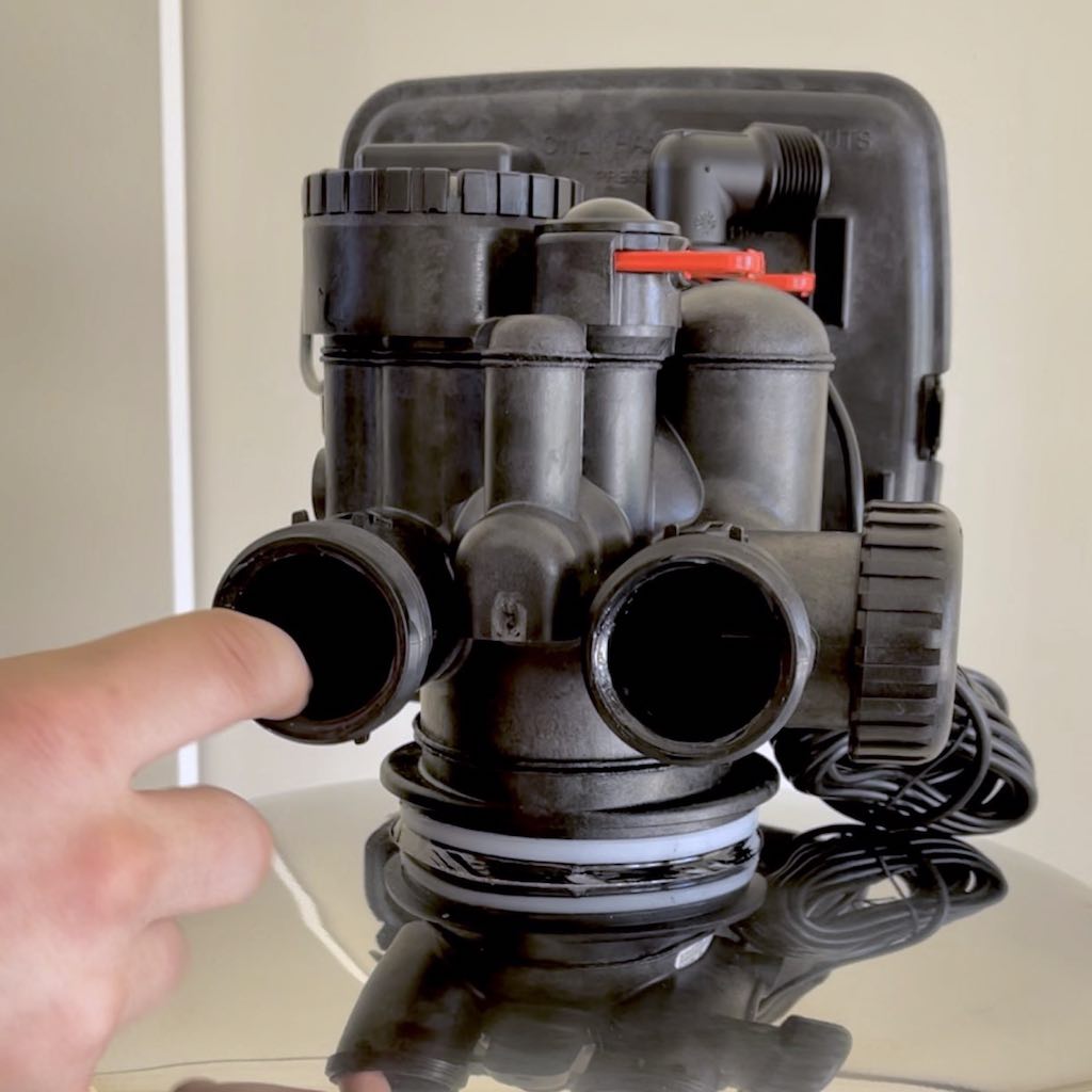
Apply plumber's grease all the way around the inside of both openings of the Head on the Carbon Media Tank.
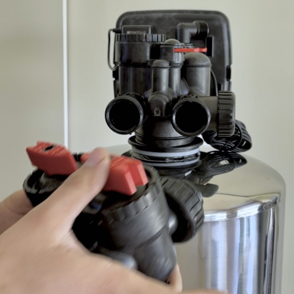
Insert the Bypass Valve into the Head of the Carbon Media Tank.
Insert the Bypass Valve into the Head of the Carbon Media Tank.
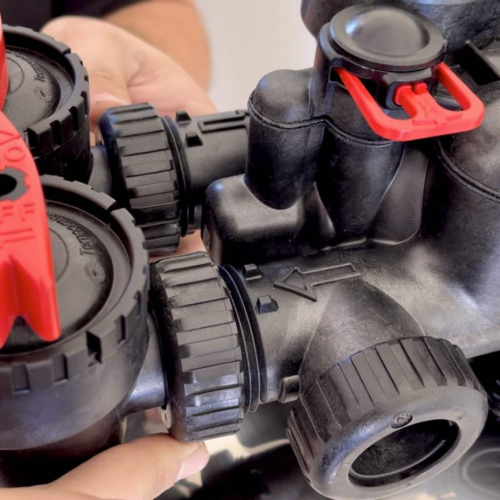
Slowly and evenly hand tighten each lock nut of the Bypass Valve.
⚠️ Do not force the O-Ring in. Let the lock nut pull the O-Ring in as you hand tighten the nut. This will prevent rolling and smashing the O-ring, which would cause a water leak.
⚠️ Do not use a wrench when tightening each lock nut of the Bypass Valve. Hand tighten only.
The Bypass Valve is now securely attached to the Head of the Carbon Media Tank.
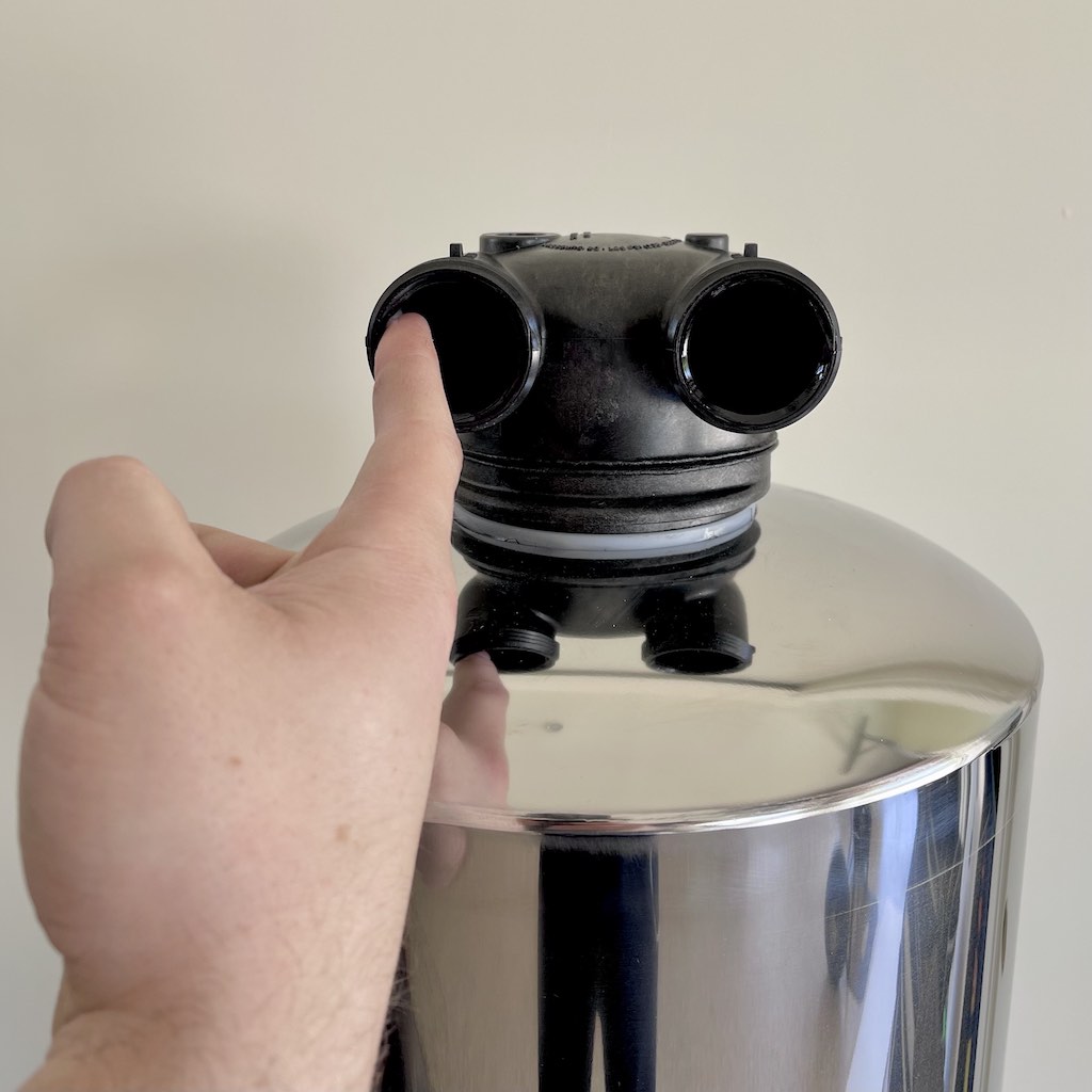
The ScaleStop Media Tank has a Head at the top. It does not have the Controller on the top.
Check Bypass Valve to ensure that the orientation is correct (view video below for details).
Apply plumber's grease all the way around the exterior threads of both openings of the Bypass Valve.
Apply plumber's grease all the way around the inside of both openings of the Head on the ScaleStop Media Tank.
Insert the Bypass Valve into the Head of the ScaleStop Media Tank.
Insert the Bypass Valve into the Head of the ScaleStop Media Tank.
Slowly and evenly hand tighten each lock nut of the Bypass Valve.
⚠️ Do not force the O-Ring in. Let the lock nut pull the O-Ring in as you hand tighten the nut. This will prevent rolling and smashing the O-ring, which would cause a water leak.
⚠️ Do not use a wrench when tightening each lock nut of the Bypass Valve. Hand tighten only.
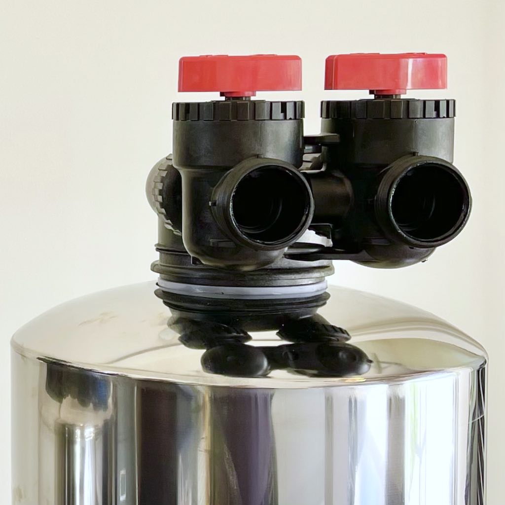
The Bypass Valve is now securely attached to the Head of the ScaleStop Media Tank.
Apply plumber's grease all the way around the interior of both openings of the Bypass Valve on the ScaleStop Media Tank.
Apply plumber's grease all the way around the interior of both openings of the Bypass Valve on the Carbon Media Tank.
The diagram below shows how the hoses are connected to the tanks.
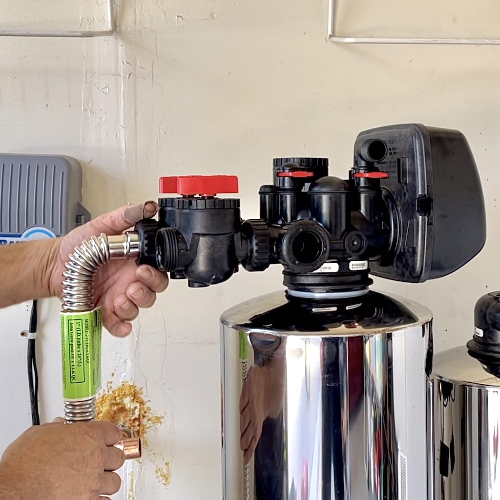
Attach the connection hoses to the Bypass Valves of each tank.
⚠️ Slowly and evenly hand tighten lock nuts on fittings and hoses (do not use a wrench).
⚠️ Do not force the O-Ring in. Let the lock nut pull the O-Ring in as you hand tighten the nut. This will prevent rolling and smashing the O-ring, which would cause a water leak.
⚠️ Do not use a wrench when tightening each lock nut of the Bypass Valve. Hand tighten only.
The next few steps involve cutting, preparing, and connecting the copper piping for the water filtration system. Below is an example of a copper piping connections diagram.
Cut copper connector and sand down the ends.
Fit straight copper connectors to copper elbows.
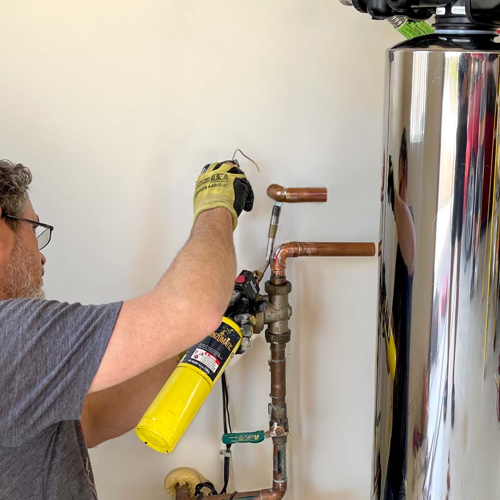
Weld copper elbow joint.
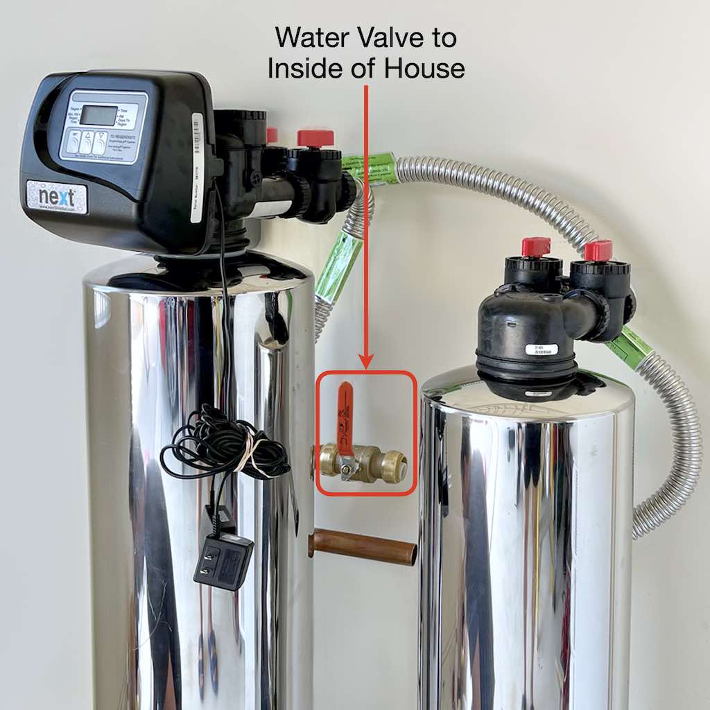
Install water line valve for water flowing from the filtration system to within the house.
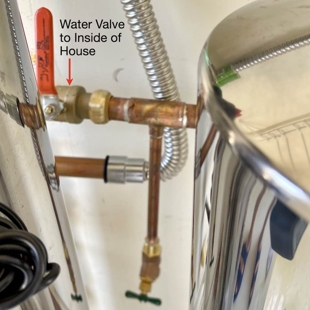
Attach copper tubing to the right of the water valve that lets the water into the house.
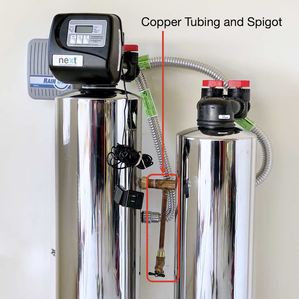
Install copper tubing and spigot, which will be used to flush Carbon Media Tank during installation.
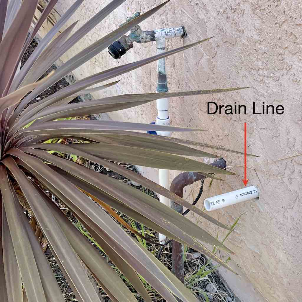
A drain line will be used to flow backwash water from the Carbon Media Tank (the tank that has the Controller) to outside of the house.
Measure section of drain line from the Carbon Media Tank.
Attach section of drain line from the Carbon Media Tank.
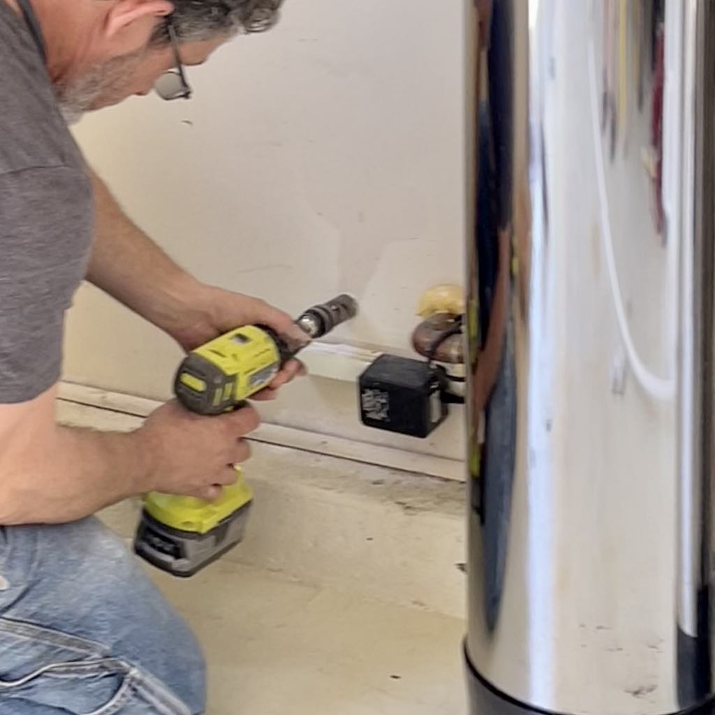
Drill hole for drain line to outside of house.
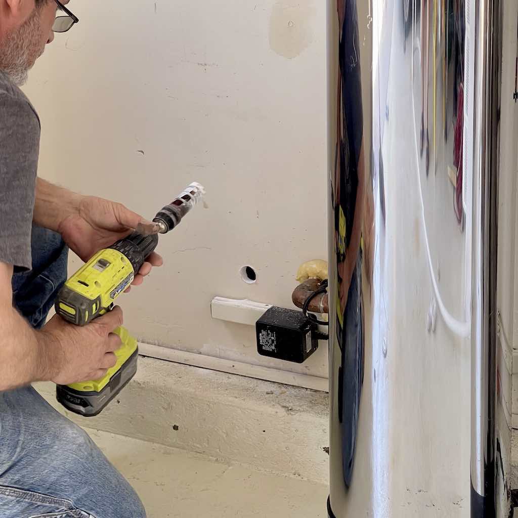
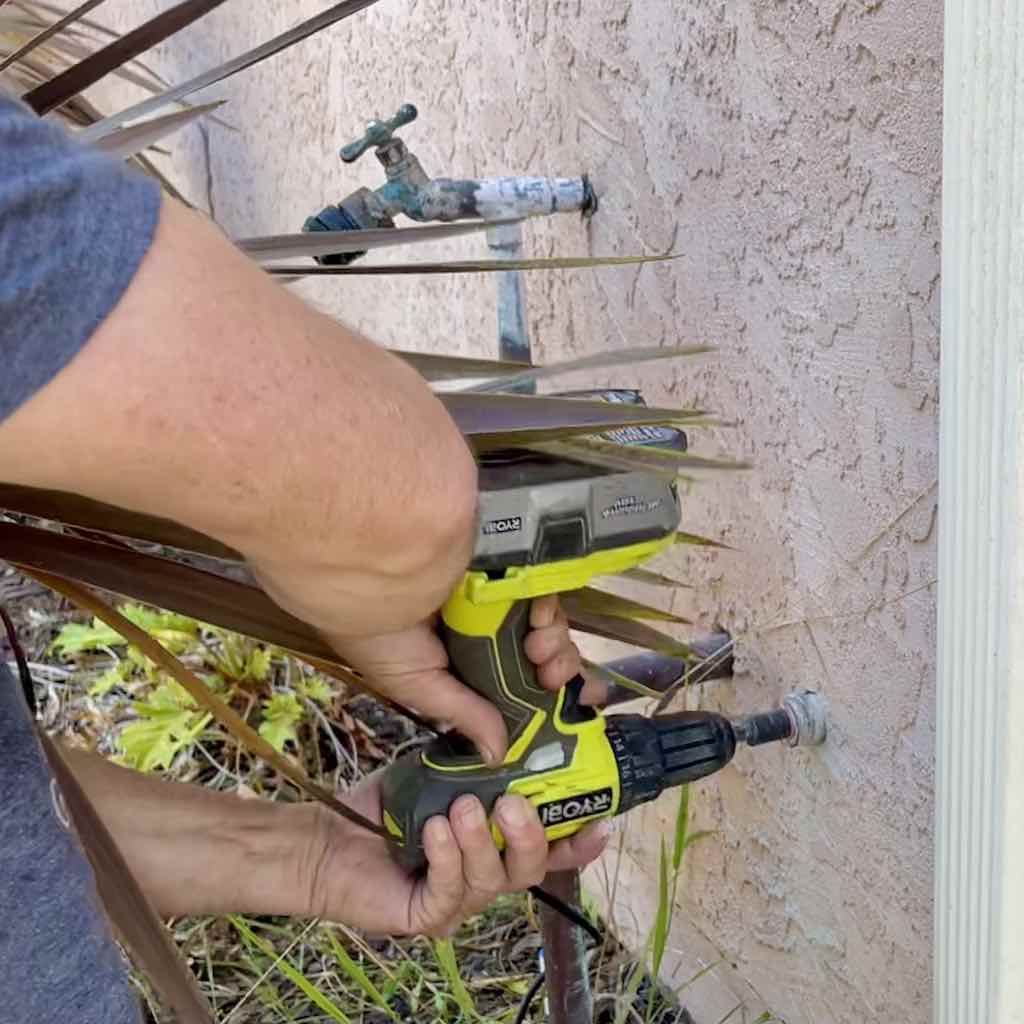
Drill hole on outside of house for drain line.
Drain line to cut to size.
Extend drain pipe from inside of the house to the outside of the house.
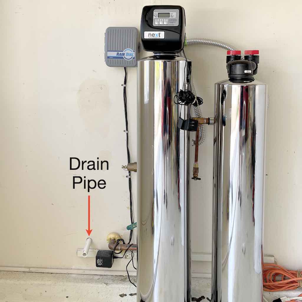
Cut the drain line that goes from inside of the house to the outside of the house.
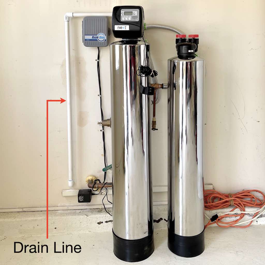
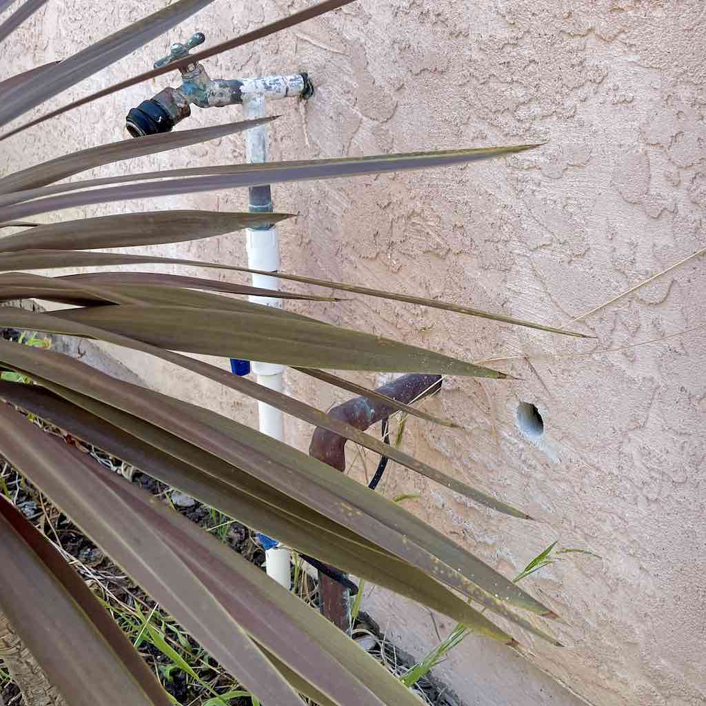
Completed drain line goes from the top of the Carbon Media Tank to outside of the house.
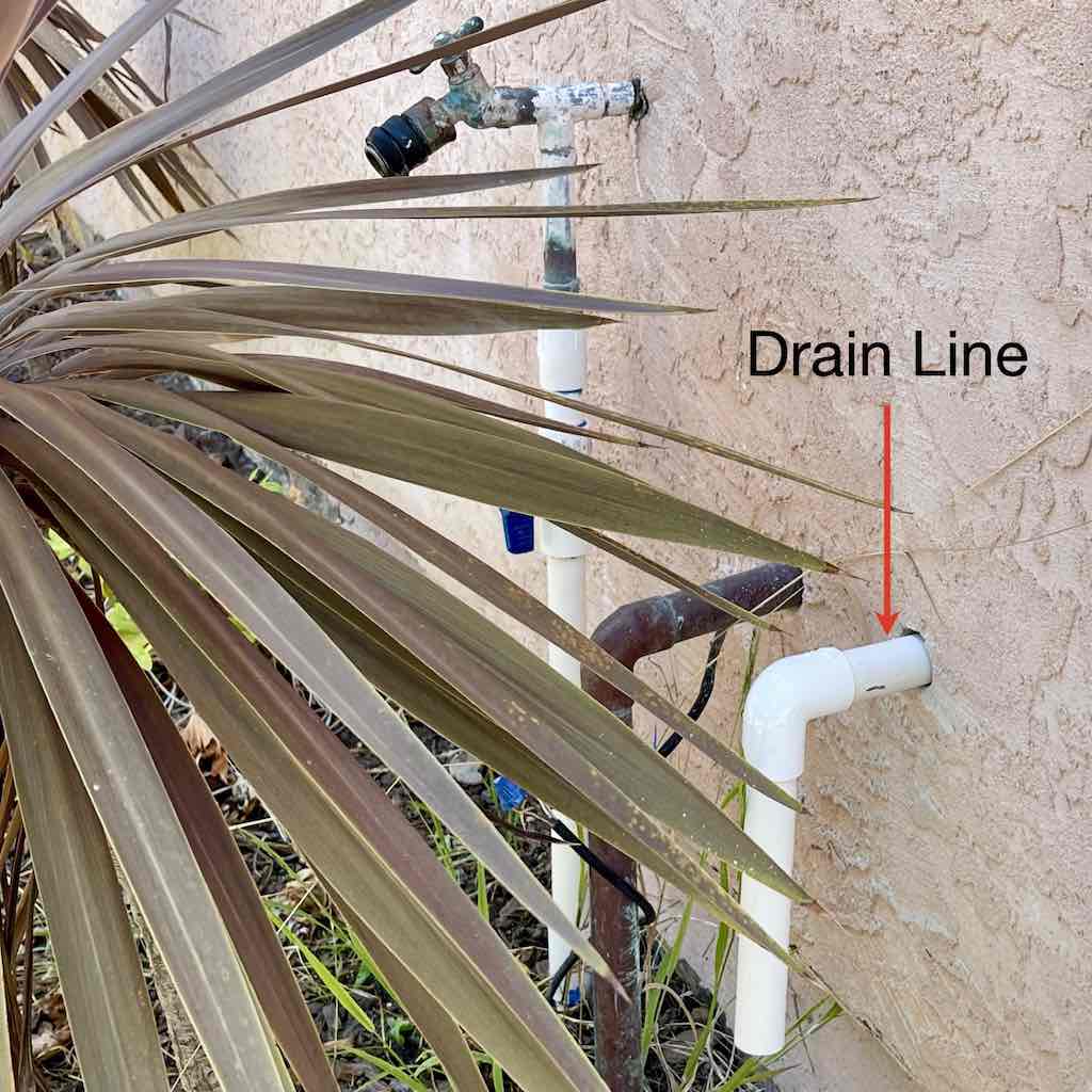
Drain line goes from inside of house to outside.
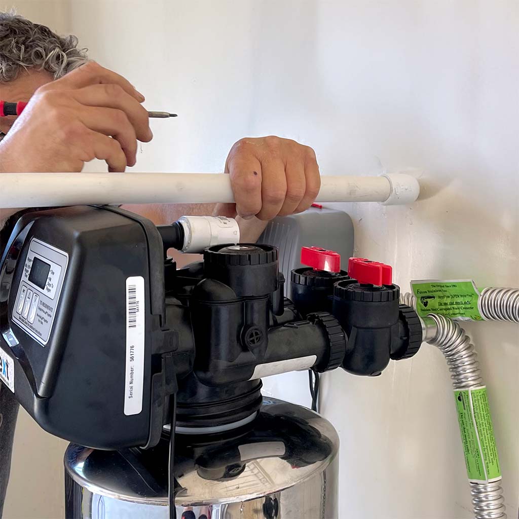
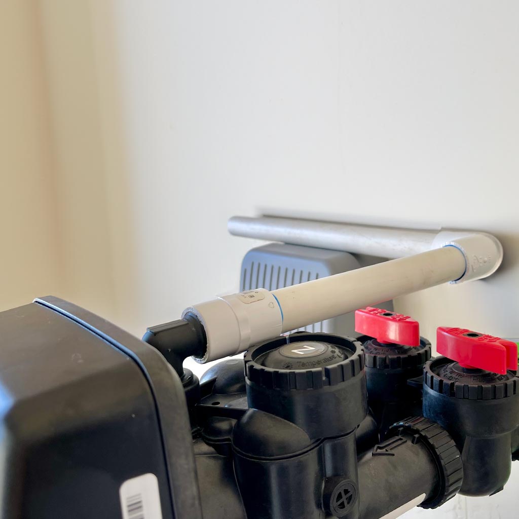
Connect the hoses from both tanks to the new copper connections and water valve into house.
The diagram below shows how the hoses are connected to the tanks.
The diagram below shows the fully connected water filtration system.
⚠️ Caution All the connections are now completed, but the system is not yet operational. The Carbon Media Tank needs to be rinsed of manufacturing residue, the entire system needs to go through two or more regeneration cycles to adequately flush it, and the Bypass Valves need to be put in the open position.
Test the water main valve to ensure it is in good working condition. If it is difficult to operate, or if it leaks, replace the water main valve.
The Carbon Media Tank must be flushed to rinse away any carbon residue from the manufacturing process, to prevent carbon residue from going into your home.
⚠️ IMPORTANT Thoroughly flush the Carbon Media Tank during installation, to ensure all the residue from the carbon media manufacturing process is rinsed away.
For optimal performance, the water filtration system requires regeneration which automatically flushes both tanks every 30 days for 15 minutes.
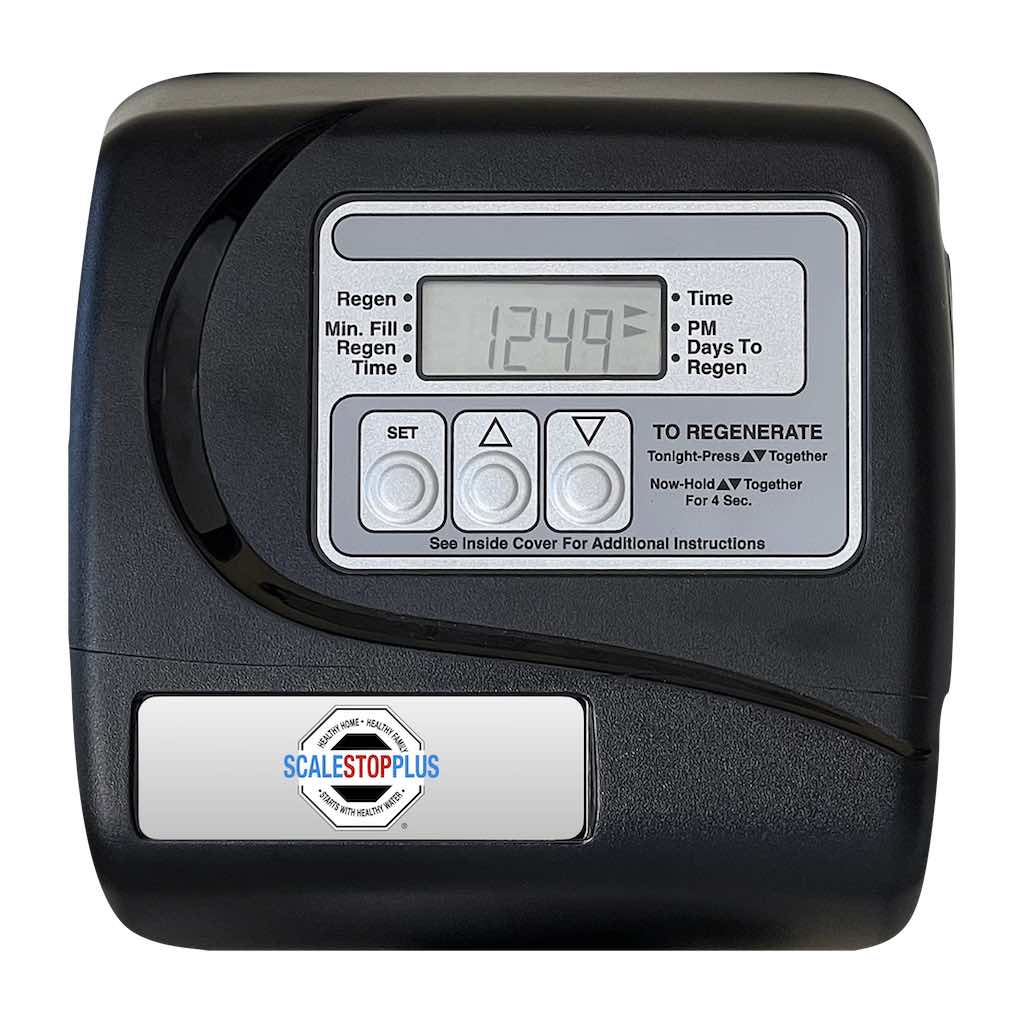
The Controller allows you to set the time and frequency of the monthly regeneration cycle. You will set the current time, then set the regeneration time to 10:00 AM, and the regeneration frequency to once every 30 days.
Plug in power cord of the Controller into a nearby electrical outlet.
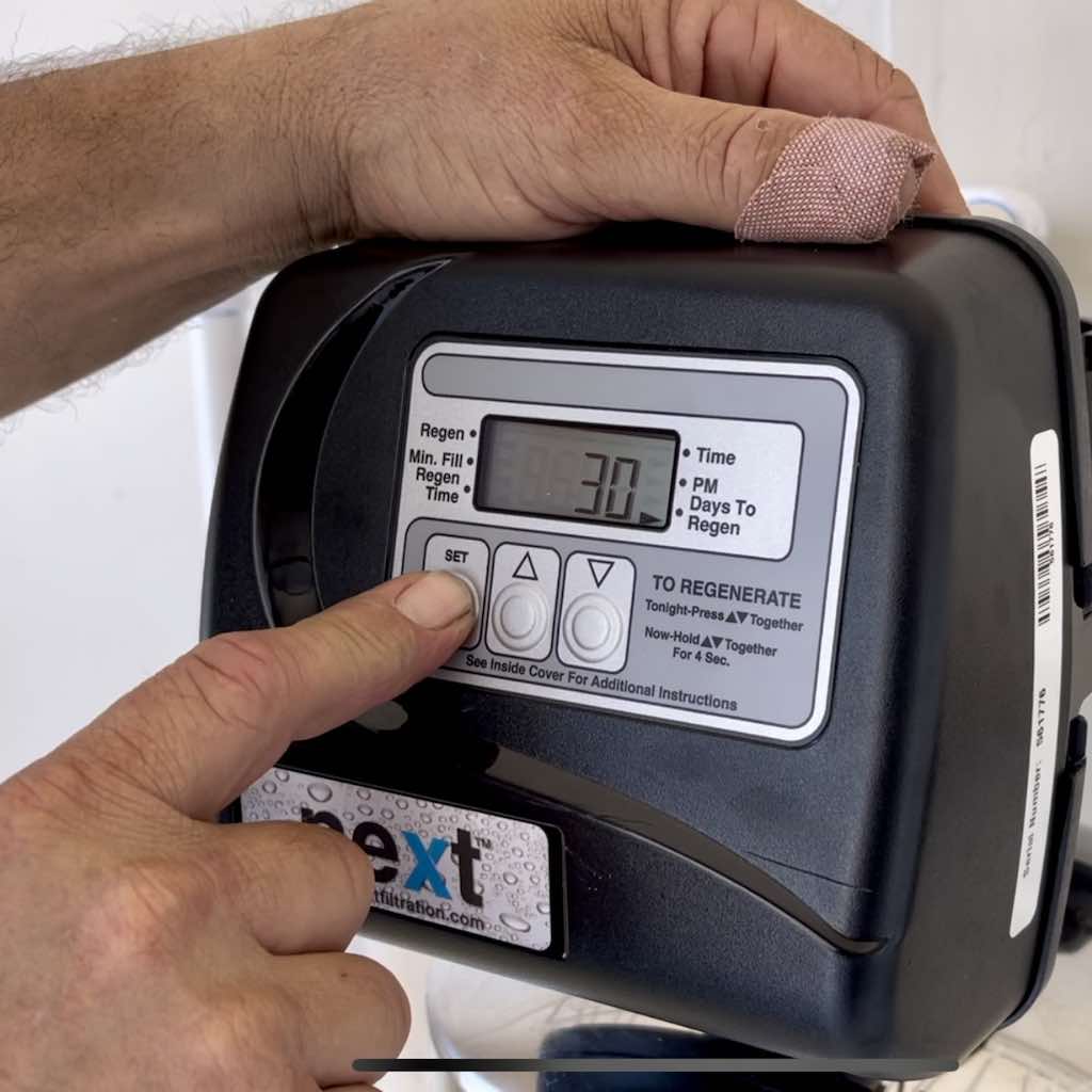
Set Current Time
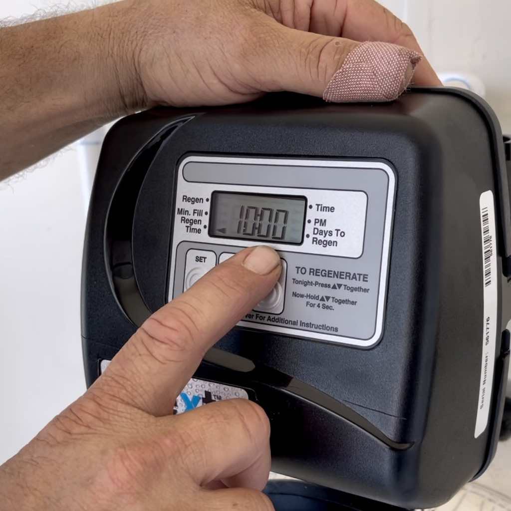
Set Regeneration Time to 10:00 AM and Frequency to Every 30 Days
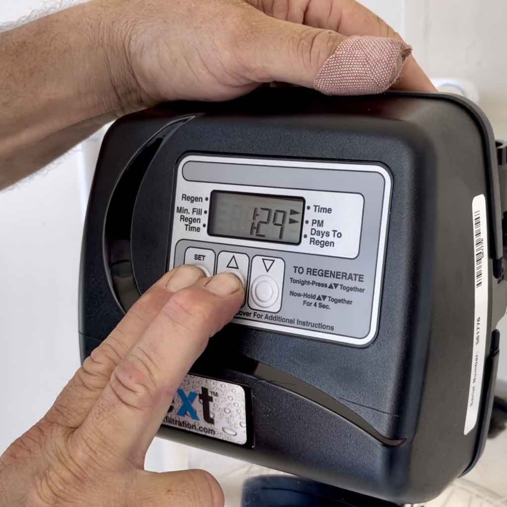
Press and hold the SET and ▲ buttons at the same time for 3 to 5 seconds. The minutes flash in the display.
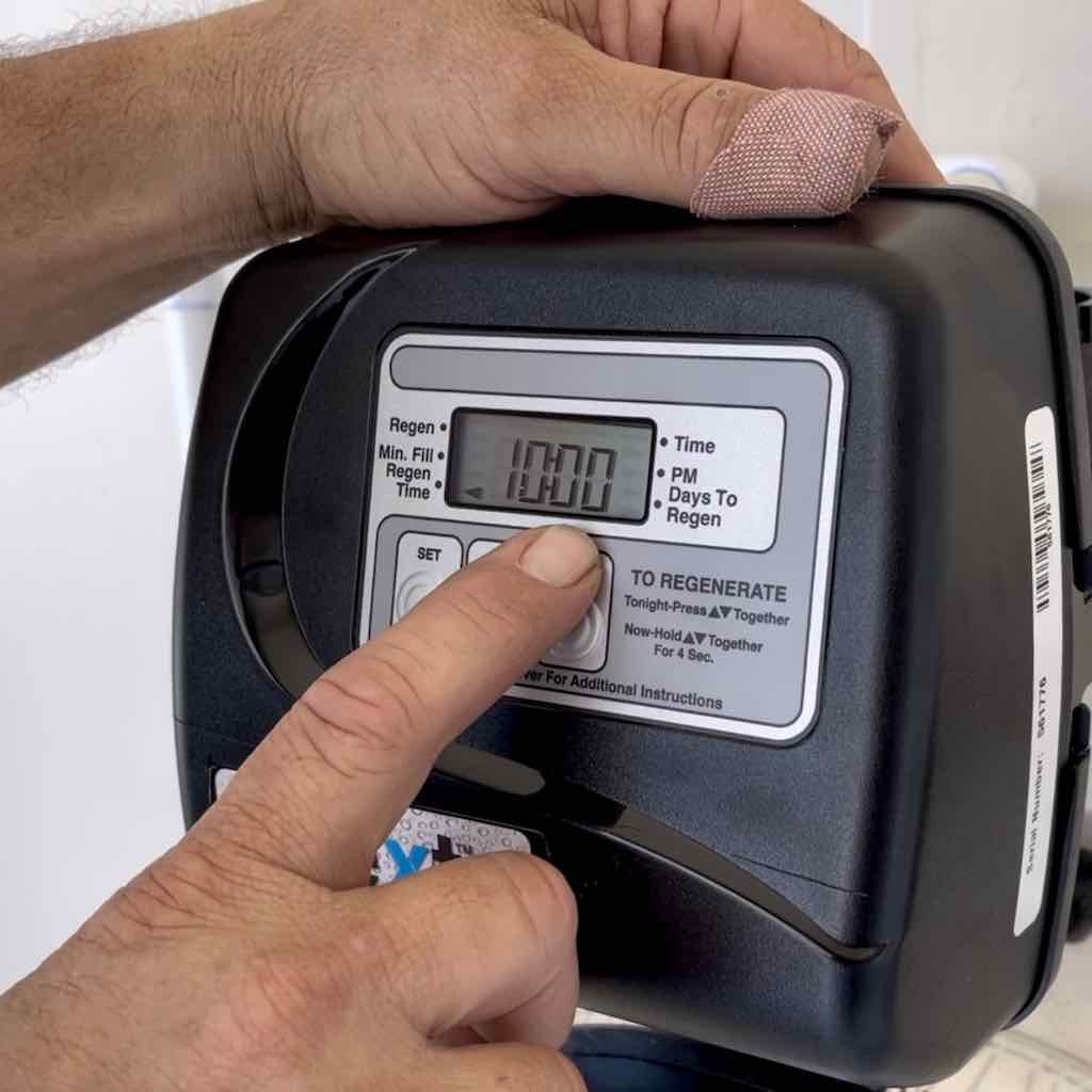
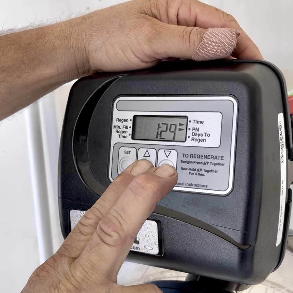
Press the ▲ or ▼ arrow to set the time to 10:00 AM.
Press the SET button to continue to set the regeneration frequency.
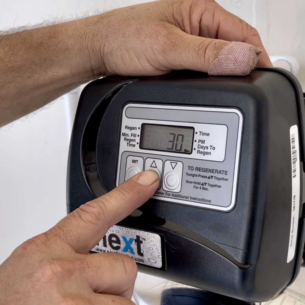
Press the ▲ or ▼ arrow to set the frequency to every 30 days.
Press the SET button when done.
Backup Battery
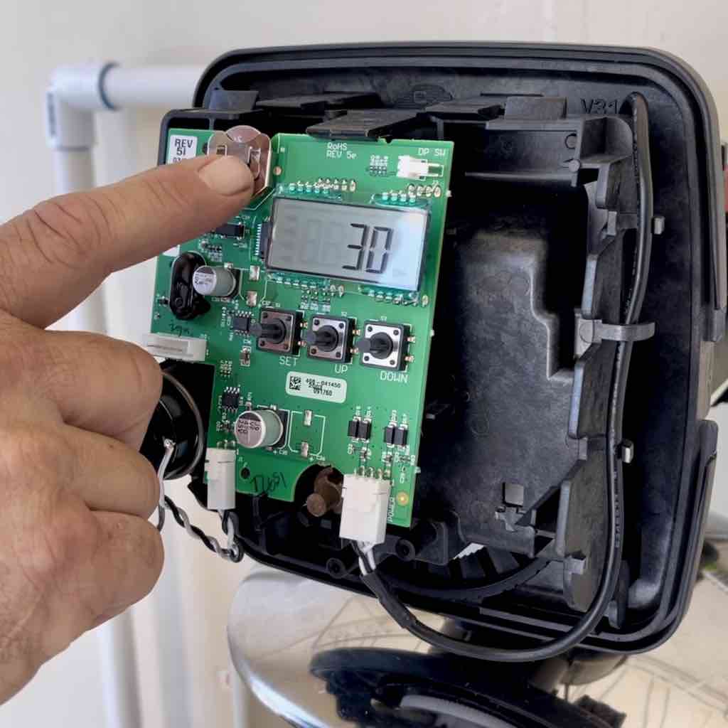
The Controller has a backup battery inside. This provide several hours of power in the event of an electrical power loss to your house.
Replace the battery every year.
The video below demonstrates how to set the Controller settings.
⚠️ Caution The Controller cannot be exposed to outdoor elements, such as direct sunlight or atmospheric precipitation. The system may be installed in a covered, open-air structure such as a carport, residential or commercial building.
For more information, click Controller Manual.
The entire water filtration system must undergo flushing to remove any particulates, sediment, or residue before use. This process is called regeneration or backwashing.
Close Valve Into House and Open Bypass Valves
Perform 2 to 3 Backwash or Regeneration Cycles
⚠️ IMPORTANT Backwash the entire system at least twice during installation, to ensure that the media in both tanks are fully flushed.
Slowly open all faucets within the house to relieve any air in the plumbing, then close them.
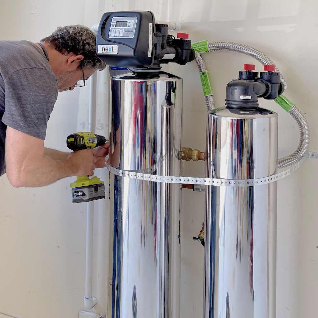
Attach metal strap around both tanks to secure them in the event of an earthquake.
The installation is complete!
Call, text message, or email us today to take the next step to clean, healthy, pure water with no hard water scale to enjoy your life and home.


 Made in USA